There have been a lot of rumors and discussion about the $99 Eachine EV100 FPV goggles recently. I already did some teardown, component analysis, component identification, and analyzed the “diversity” feature of the receiver in my previous posts.
With the goggles being more and more used, people experience a new problem with these goggles: Depending on the depicted scene a gray bar overlays the video feed and some strange distortion becomes visible: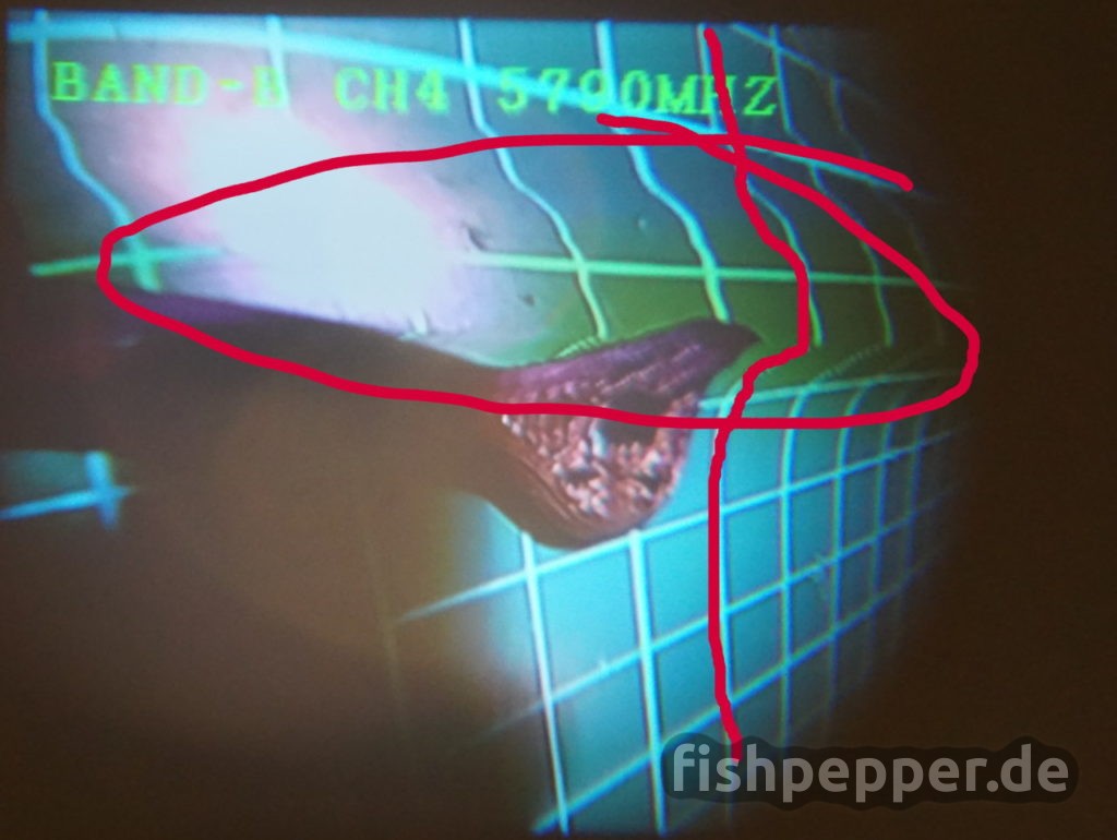
Many people were complaining about this and Eachine/banggood was promising a “firmware upgrade” soon. Well… They released a “fix” for the problem. But that’s not really a firmware upgrade. More a hardware “upgrade” or let’s say bugfix. The banggood employee (?) BGJim suggests to replace a small capacitor on the mainboard. Interesting… Let’s investigate what this changes. If you are here to see how to fix it in order to get flying again please scroll down, there is a detailed tutorial with pictures on how to swap the capacitor. Just in case you are as curious as me, you might not want to skip the following investigation of the cause and how a single capacitor fixes the issue that follows next.
Sync issues?
Before BGJim posted the fix I already had an idea what was causing this. I have been digging into the “wonderful” world of analog PAL/NTSC video signals the past months while designing my custom tinyOSD project and this looked like a bad line sync to me. This gray/dark bar always happens together with some strange image distortion you can see in the previous picture.
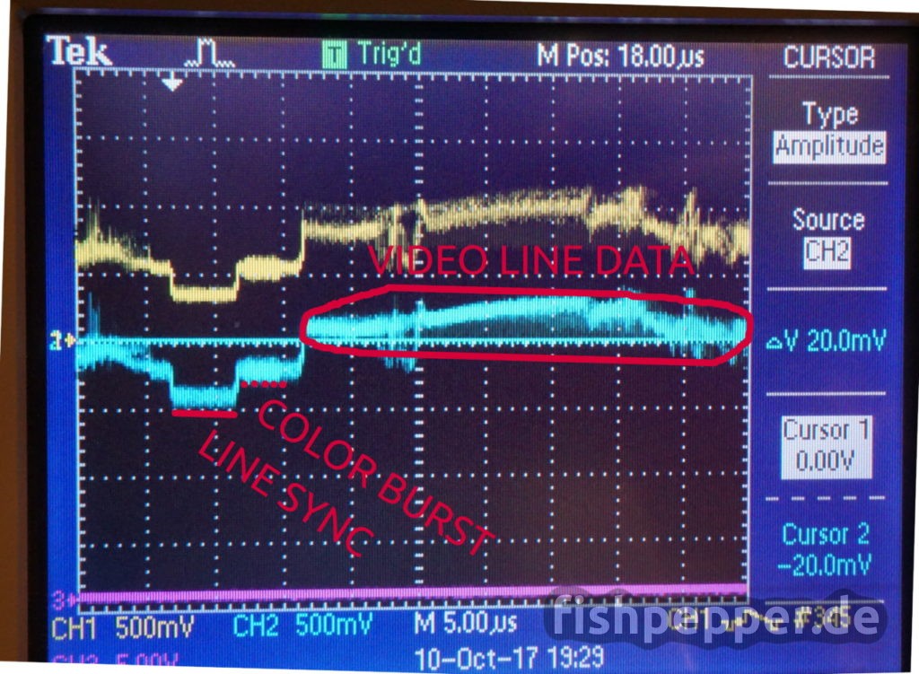
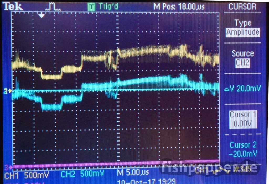
An analog video signal consists of different sync signals that basically tell the “television” when to start a new line or frame. Remember, this is all analog, so different voltage levels stand for different parts of the signal. Let’s have a look at the following scope picture (ignore the yellow signal for now):
I am going to keep it simple, in reality things are a bit more complicated. The line sync signal can be seen at the left, followed by a color burst signal, and finally one analog representation of a single video line. Now comes the hard part: which voltage level represents a line sync, which is data?
This is where the PAL and NTSC standard define voltage levels for this type of signals. The sync level is specified at -0.3V, a black “pixel” is represented by 0V and a white “pixel” is around 0.7V. So this is where things get complicated. Various things can cause the signal to shift up or down. This is why AC coupling is used to get rid of this artifacts. You basically add a capacitor in line with the signal to block any DC (= very low frequency with 0 Hz) components of the signal and let only high frequency parts of the signal pass. Maxim has written a really great (but technical) article on this, you can find it here. An excerpt reads:
Using too small a capacitor causes the displayed image to darken from left to right, top to bottom, and can distort the image spatially (depending on the capacitor’s size). In video, this is called line droop and field tilt.
Wait, this sounds familar, right? But more on this later…
Analysis
BGJim suggests to replace a specific capacitor with 2x 100 uF tantalum capacitors which sum up to 200uF capacity. If you read my blog regularly, you will know that random try’n’error part replacements are not my thing. I want to know exactly what is going on. So let’s have a look at the capacitor and how it is connected:
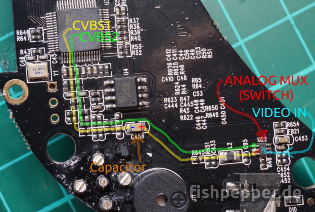
The video signal originates from the right (cyan), passes a 3157 video mux (which is an electronically controllable switch) and can take either the green or yellow path, depending on the mux status. The yellow path is passing our mystical “firmware” fix capacitor. In addition, both signal paths have a lot of unpopulated filtering and signal reconditioning pads. The designer of this PCB knew what he was doing, he was prepared for a lot of filtering that might become necessary during testing.
The populated part of the filtering circuit looks like what is used on a reference design for a similar chip (MST702 SZDEMO). The CVBS1 and CVBS2 pins of the video decoder (MST706) are just analog video inputs. I did not investigate further when the signal passes the green or yellow path but I would expect analog video input will be routed the green path as external devices usually contain the AC decoupling capacitor.
Scope pictures
So what does this AC coupling capacitor do to your signal? How does this look like? Let’s hook up a scope to the capacitor in order to see the voltage levels before and after passing the capacitor.
The yellow plot shows the signal before passing the capacitor and the blue one is the signal right behind the capacitor. You can see that the yellow signal is all positive and has an offset of around 500mV to the blue one. The blue one looks better, most of the offset has been removed by the AC coupling.
You might ask why this is necessary? Well, a PAL or NTSC signal is defined to have certain voltage levels and the input stages have some voltage limits they can deal with. A signal shifted to high might damage the input stage or might not get “decoded” properly. This is what is happening here, depending on the video signal, the signal behind the AC decoupling capacitor (blue) can still contain a DC offset when the capacitor is to small. This causes the “decoder” to misinterpret or miss the start of line voltage level and thus creating the artifacts we see.
In case you are curious what capacity Eachine used: I desoldered the capacitor and measured it: My (crappy) multimeter reads 23 uF, this looks quite small. BGJim recommends to replace it with 200uF. So let’s do it!
Tutorial
This modification is not that hard to do. It’s a pity that this was delivered to thousands of customers and was neither found during initial testing or by the beta reviewers. If you know some tricks this modification could be done by many people of the quadcopter building scene, but be warned, I do not know how Eachine will handle any warranty claims when you soldered stuff to the PCB on your own. Most likely this will void warranty. Anyway, here is a do-it-on-your-own risk tutorial:
[0] Things you need
Of course you will need a soldering Iron. In addition you will need a capacitor that is large enough. The exact type will probably not matter, I have seen tantalum, ceramic and electrolytic capacitors for AC decoupling in Chinese AV gear before. In my opinion for most of the users it would be the easiest way to solder a wired capacitor to the pads. I used a 220uF 16V electrolytic capacitor for this (e.g. one out of this set should do). You can also add the capacitor in parallel to the existing cap. There is plenty of room for the capacitor.
[1] Open the case
Unsnap the face plate and use a cross screwdriver to remove the screws on the bottom:
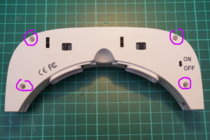 Use a plastic card or your finger nail to unsnap the plastic retainer hooks in the front.
[2] Remove the PCB
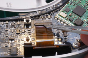
Unscrew the PCB, open the flex cable connectors, and remove the flex cables.
Remove the fan on/off switch connector and remove the PCB.
[3] Desolder the capacitor
This step is optional, you could also leave the original one connected and solder the new one on top of the old one. Both capacitances will add. There are reports on rcgroups that 47-220uF in parallel fixed the issue.
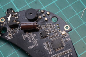
Removing the old capacitor looks complicated at first, but with a neat trick it becomes be quite easy: Take a medium or big solder tip and add some tin. Now hold it on top of the original capacitor. Make sure to have contact with both sides. The capacitor will now get desoldered and most likely will stick to your soldering tip. If not, use a tweezer to remove it. 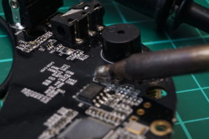
(Sorry for the bad picture, I noticed it to late that this is defocussed a “bit”…)
[4] Add the new capacitor
Now take your capacitor. BGJim recommends to have the minus side of the capacitor towards the incoming signal (remember, tantalum caps have marks on the positive side!). Most video AC coupling circuits I have seen (e.g. this one by maxim) connect the positive side towards the signal, see the plus sign in this picture. I am quite sure this does not really matter in this application as the voltage difference is only 0.5V. Electrolytic capacitors behave bipolar for voltages of less that 1.0-1.5 V.
[5] Check for shorts & Solder blobs
You are almost done. Do a short visual inspection for any shorts or soldering blobs that might got distributed during your soldering.
[6] Assembly
Re-assemble the goggles and enjoy your next FPV session without those annoying gray bars. That’s all for now.
What’s next?
I am still investigating the inner workings of this FPV goggle. However, right now I concentrate on finishing my new 16x16mm ESC design. You can expect an all new micro brushless quadcopter design similar to my 45g 2S pepperFIISH design soon. Stay tuned, you will not regret it! If you liked this blog post and want to support future work you can use this link to visit banggood the next time you go shopping. This is an affiliate link, this does not cost you a cent but I will get a small provision from banggood whenever you make a purchase after you clicked that link. This helps me to acquire new stuff and write tutorials like this. Thanks a lot for your support!
A list of previous and newer posts regarding the EV100 can be found in this list:
- Eachine EV100 component analysis: Display module supplier and technical data — UPDATE (12/3/2017)
- Eachine EV100: no audio problem — cause, fix, and technical background — UPDATE (10/24/2017)
- Eachine EV100: no audio problem — cause, fix, and technical background (10/20/2017)
- Eachine EV100 component analysis: Video receiver module identified — Sinopine SP338RX (10/12/2017)
- Eachine EV100: gray bar & distorted image problem — cause, fix, and technical background (10/11/2017)
- Eachine EV100 component analysis: Video decoder chipset identified — MST706 (9/27/2017)
- Eachine EV100 diversity: to be, or not to be, that is the question! (9/22/2017)
- Eachine EV100 component analysis: Display module supplier and technical data (9/20/2017)
- Eachine EV100 $99 FPV goggle — Disassembly, Components & PCB pictures (9/18/2017)

Hi,
Would you know what is the part number or where couldni get the component on U22? The analog switch mixer.
I have no continuity from blue video in to 3 pins green red yellow on the pics.
Thanks
This should be a sn74lvc1g3157. You can try mouser: https://www.mouser.de/Texas-Instruments/Semiconductors/Switch-ICs/Analog-Switch-ICs/SN74LVC1G3157-Series/_/N-7590c?P=1yxz4icZ1z0zls6
Just make sure to order the right package 😉
Hi!
Is there any easy way to disable the inbuilt OSD of the goggles? Maybe instead of feeding video on the receiver pads it is possible to bypass it and feed after the chip that is in charge of controlling the osd?
I’m using the eachine pro 58 and since I can’t use the Google ch up/down buttons to control it I wanted to hide/detach ev100 buttons on my custom 3d printed case, unfortunately i cant do that because i need them to turn off the green osd…
Or maybe it is possible to control the eachine pro58 module with the ev100 ch up/down buttons?
I tried connecting the ch1 ch2 ch3 of the module to the original rx pads but with no luck…
The goggle OSD can be toggled on/off by pressing the channel up and down buttons at the same time
Replaced the capacitor but wasn’t getting any video output after, tried soldering the legs but now the + side trace has come away from the board.
Any work around?
You can follow the tracks by using this picture as a reference. Soilder the open end of the cap to a pad that was connected to the pad by a trace before.
Hello. I have a pair of these and it is the 1.2 version. Where you have only 1 cap, I have 2 side by side. And I’m still getting the distortion lines running through the whole center of the screen. I’ve tried 1 cap at 25v 220uf with no success. So I tried a cap on each one of them at 25v 220uf and still get the lines. It’s definitely the goggles as I have tried multiple runcam and many other off brands. So should I try removing both original caps and then solder the new ones on? I’m really new to this and don’t know more then I’ve read here and anywhere else I can find it lol so I’d really appreciate any help I could get. Thanks in advance and have a great day.
When your goggles have two in parallel then yours should be the fixed version already. So maybe your problem is not related to that fix. Try to contact the support where you bought them, e.g. banggood seems very responsive and helpful on problems you have with those goggles. At least I heard so from others 🙂
Just to share some findings on EV100 reception, I find that it has quite some interferences even at short range, the antennas were bot good, plenty of signal.
However I find out by a surprise I could still receive the drone up to 100m around even with both antenna’s completely disconnected from the EV100!!!, so at least this RX is sensitive, but likley there may be some mismatch in the antenna lines or pcb switch circuitry? The open lines or unshielded pcb pick up signal directly, so this is definitively no good……
It also means with antenna’s connected, with a mismatch or unshielded stripline etc they are probably badly used, loosing there signal…..
The stripline looks like it is not matched. However it is really short and they used a coax cable to connect to the second antenna so this should do. I experienced the good reception without antennas as well, I do all my ev100 testing without antennas connected :-X
Dear fishpepper,
With rising shtonishment I have read virtually all there ia vailable on your website.
I am especially interested in the 1squadcopter projects. I am amazed by your design (and loathe the fact that there is no reference to you on certain copycat websites).
However. I still feel there are 2 things that need to be solved in order to heve the cleanest build possible and I have great admiration for your electronics capabalities, so I am asking you… I am looking for a. a dms2/x receiver with in format 16×16 or 20×20 with mountin holes so it can be put on a ‘stack/tower’ b. The same applies for VTX modules. (should be 25/200mW) I want the camera to be separate from the VTX like with the KK90Gt. Neither seem to exist. I did find the furious FC with integrated dmsx RX but it seems to be the olny one. Would it be of any interest to you to design, bash/hack such components ? I would certainly buy them from you! Many thanks in advance! Greetings and keep up your wonderfull work and progress…
Thanks!
I do not have any spectrum gear and thus my designs are FrSky based…
In addition I know the Frsky protocol quite well, I have been working with it
for several years now.
Concerning the stack: A 16×16 vtx and OSD pcb is in the works, just needs further software hacking.
The prototypes work and I need to get the bf integration done. Just a matter of finding more time for it.
This is the kind of work that I do not like doing when I have 30minutes for working on my projects, for
HW hacking/designing this is fine. For serious software development I like to have more time in a row.
That’s why this is not yet ready 😉
Mine has an other problem. I can’t find it in the forums but my picture looks like it has an 256 color pallete.
Adjusting the contrast doesn’t work for the problem. Hope you or somebody can help me.
Have a look at the ribbon cables from the displays. Maybe remove and reinsert them.
Thanks for sharing!
Wondering when new 3d printable faceplates pop up for EV100, I find the googles much better, actually really good, when I have the goggles closer to my face, only thin layer of foam. The image becomes bigger and more easy on the eyes.
Fernandez : just order some fatshark foam padding replacements, they are much much thinner and fit well on the ev100’s. I did this on the first day 🙂
1. Will a 220uF 25V (instead of 16V) also do it? I still have lots of them here…
2. Which of both solder pads is + and which one is – ??
The voltage does not matter. I just updated the picture in the post, this should make it a bit more clear where to solder the positive terminal 😉
Thanks a lot for putting this together. Just wondering why you remove the original cap?
One could just solder the larger capacitor on top of the existing one. Probably more easy to solder for beginners.
Sure you can keep the original capacitor. I modified the post to make it more clear that you can keep the old one. 🙂
Anyway I had to desolder it in order to measure the capacity, I was curious how far the original one was off 🙂
Does this mean all of myEV100 issues (jittery image, screen flashing black, gray bars) will not be fixed with a simple firmware update as promised by Eachine/Bangood?? 😐
Unfortunately no. This capacitor will fix jittery/distorted image and gray bars.
The black screens are (most likely) caused by the receiver modules firmware. Not sure if they can upgrade this via USB.
Great tutorial! Thanks
Hope there is fix for the audio output as well!
Thanks for all your work. Im a big fan.
Can’t wait for the 2S quadcopter. 🙂