TinyWhat?? A safe ultra micro FPV racer!
 After seeing this video i got infected by the TinyWhoop virus… So what is a TinyWhoop? Basically it is a modified Blade Inductrix Quadcopter with added FPV gear. It became very popular recently and even HorizonHobby started selling an Inductrix FPV edition.
As this hobby is all about building stuff and learning on the way, i will go the more exciting way by building my own version. In contrast to other builds i am going to use an universal micro flight controller board with an STM32F3 CPU. The reason is simple: I do not want to be stuck with the Inductrix flight controller, i prefer having a controller that can run my favorite flight controller software (betaflight). As the community moves towards F3 or even F4 targets i choose a future-proof F3 based board for this build.
Shopping…
First of all it’s time for shopping! My build is based on the original Blade Inductrix frame that you can buy as spare part. All in all i bought the following parts:
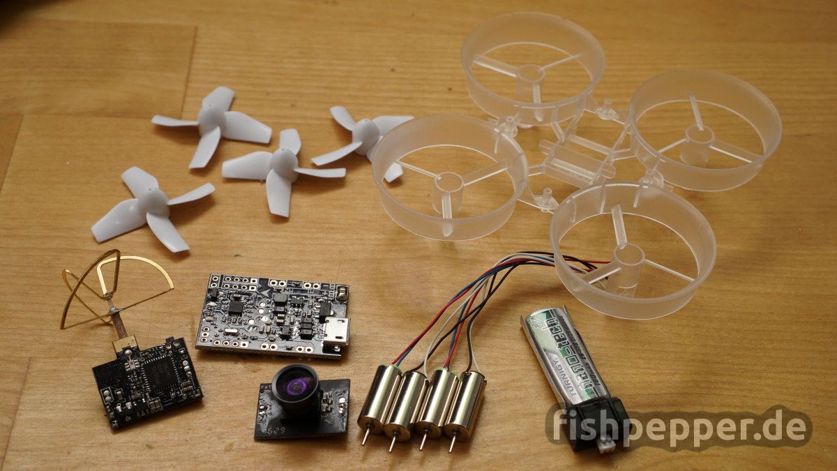
 Motors: a set of 4 Chaoli motors (fast)
- Flight Controller: Micro brushed F3 (SPRACINGF3EVO Clone)
- FPV Camera (incl. transmitter): FX987T 5.8Ghz 40CH allinone
- Frame: original Blade Inductrix Frame (alternative link to amazon.de)
- Propeller: original Blade Inductrix
- Battery: for now Turnigy nano 160mAh, will upgrade to 205mAh once back in stock
- Receiver: uSky — my custom 0.37g Frsky SBUS RX

I took some weight measurments on arrival:
| Item | Comment | Weight |
|---|---|---|
| F3 Flight controller | Micro brushed F3 SPRACINGF3EVO clone | 2.9g |
| Camera | FX987T 5.8Ghz 40CH (stripped) | 3.56g |
| Frame | original Blade Inductrix | 3.2g |
| Propeller | original Blade Inductrix | 4x0.27g = 1.06g |
| Motor | Chaoli fast (stripped) | 4x1.83g = 7.32g |
| Case | custom vacuum formed | 0.7g |
| Battery | Turnigy nano 160mAh | 4.12g |
| Receiver | DIY Frsky SBUS receiver | 0.5g |
Including my RX (not shown) this adds up to a total of ~ 22.5grams – nice! Some more weight will be added by additional brackets, cables etc. but still, this sounds promising.
3D printed parts
The flight controller used in my build does not fit the mounting holes of the standard frame. This is why i had to design custom attachment parts. You can find the STL files of these brackets on my Thingyverse account. Download the STL files and print the configuration you like (0°, 10°, 20°, or 30° camera angle). I used two perimeters, 30% infill and top- and bottom-width of 0.8mm and printed slowly in 0.2mm layer height.
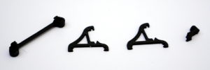
After printing the parts need some minor cleanup. First check if the flightcontroller bracket holes fit to the frame, you might have to use a 2mm drill to clean them. Depending on your printer you might have to clean up the broader first layer of all brackets.
Assembly
The next steps will guide you through the assembly of the F3 based TinyWhoop.
Preparing the camera
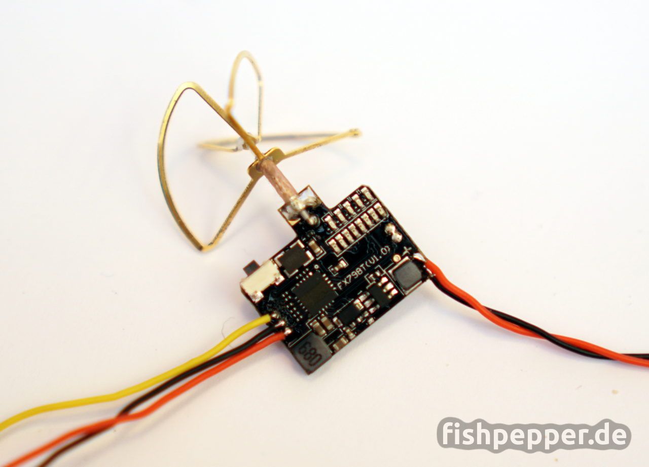
Before we start with the assembly we will have to prepare the camera. First, remove the case by bending the two plastic clips on the side and gently pulling the PCBs to the back. Now use a soldering tip with a bit blob of solder to heat up the 3- and 2-pin connector in order to separate both PCBs. Remove the plug connectors and cleanup any shorts after separation.
Next, with the VTX PCB laying on the side where the switch is, gently bend the antenna upwards. Attach three wires that will later connect to the camera to the VTX, i used black for ground, yellow for the video signal, and red for vcc. In addition to that, connect two wires to the battery input terminals of the VTX and wrap the PCB in a thin layer of kapton tape.
Preparing the frame
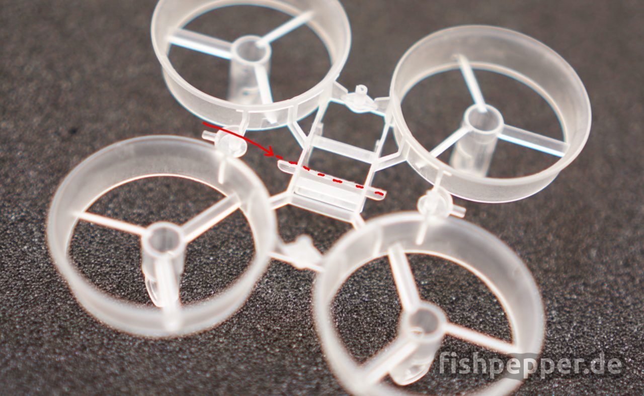
Use a sharp plier to remove the marked portion of the frame. The removed part would collide with the VTX when mounted below the flight controller.
Insert the motors into the frame holes. The motors with red/blue wires will rotate clockwise (CW) and the black/white ones anti-clockwise (CCW). Make sure to use the original assignment, these small motors have a direction of rotation and are not meant to be reversed by swapping the supply pins. If you are used to the motor arrangement in betaflight you might notice that the propellers will all spin in the opposite direction than betaflight expects. Don’t be tempted to physically swap the motors, the ducted fan design of the frame has the motor holding beams skewed, switching the direction of rotation will result in poor performance! We will correct this in software by using a custom motor mixer setting.

The motors can be pushed in completely, there is a physical end stop. Use some tape to fixate the motor wires to the outside of the motor mount.
Assembling the flight controller
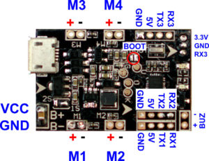
The RX will be placed below the flight controller on the quadcopters’ front. Solder the GND, 3.3V and SBUS to the DSM connection to the bottom pads on the lower left of the board. Additionally connect the hub telemetry cable to TX2.
Solder your battery connector cable and two thinner cables for powering the camera to the designated B+ and B- pads.
Take the flight controller bracket and mount it on the F3 board. Make sure to have it oriented the same way as shown in the picture. Insert the VTX into the frame and make sure the wires exit to the copters’ back.
Mounting the motors
When mounting the motors to the flight controller, make sure not to swap the polarity of the motors. Connect white and red to plus- , and black and blue to the minus-pin of the motor connectors. As written before we are going to use a custom mixer setting to correct for inverted motor rotation thus we will use the custom mixer to re-map the motors as well. This way we can solder the motors to the pads that are the closest to each motor:
M2+ = front left white     M1+ = front right red
M2- = front left black     M1- = front right blue

M4+ = back left red        M3+ = back right white
M4- = back left blue       M3- = back right black
Solder the wires according to this scheme to the bottom of the flight control board. Make sure to keep the solder as flat as possible, the camera brackets will be mounted at the same location later on. DO NOT connect the propellers yet. They might not kill you if something goes wrong during configuration as other quads do but we want to avoid unnecessary flips and rolls for now 😉

Final assembly
Next, use some sticky, double sided foam tape to mount the RX between the frame and the flight controller. Add some of this tape on the lower part of the VTX as well and plug the flight controller bracket into the frame. Attach two camera brackets of your choice to the flight controller and use a short rubber band to secure the whole structure to the frame.
Now it is time to mount the camera, connect the three cables from the VTX to the pads as they were connected before separation. It is a bit tricky to mount the camera into the brackets, do not apply to much force as the brackets might break. Make sure to get the rotation right, the text on the pcb should be readable when the quadcopter rests on his legs 😉
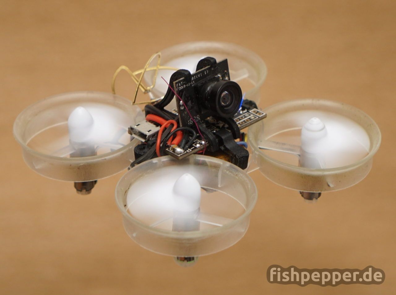
If nothing went wrong you should be done with the main assembly now. Your new copter should look similar to this: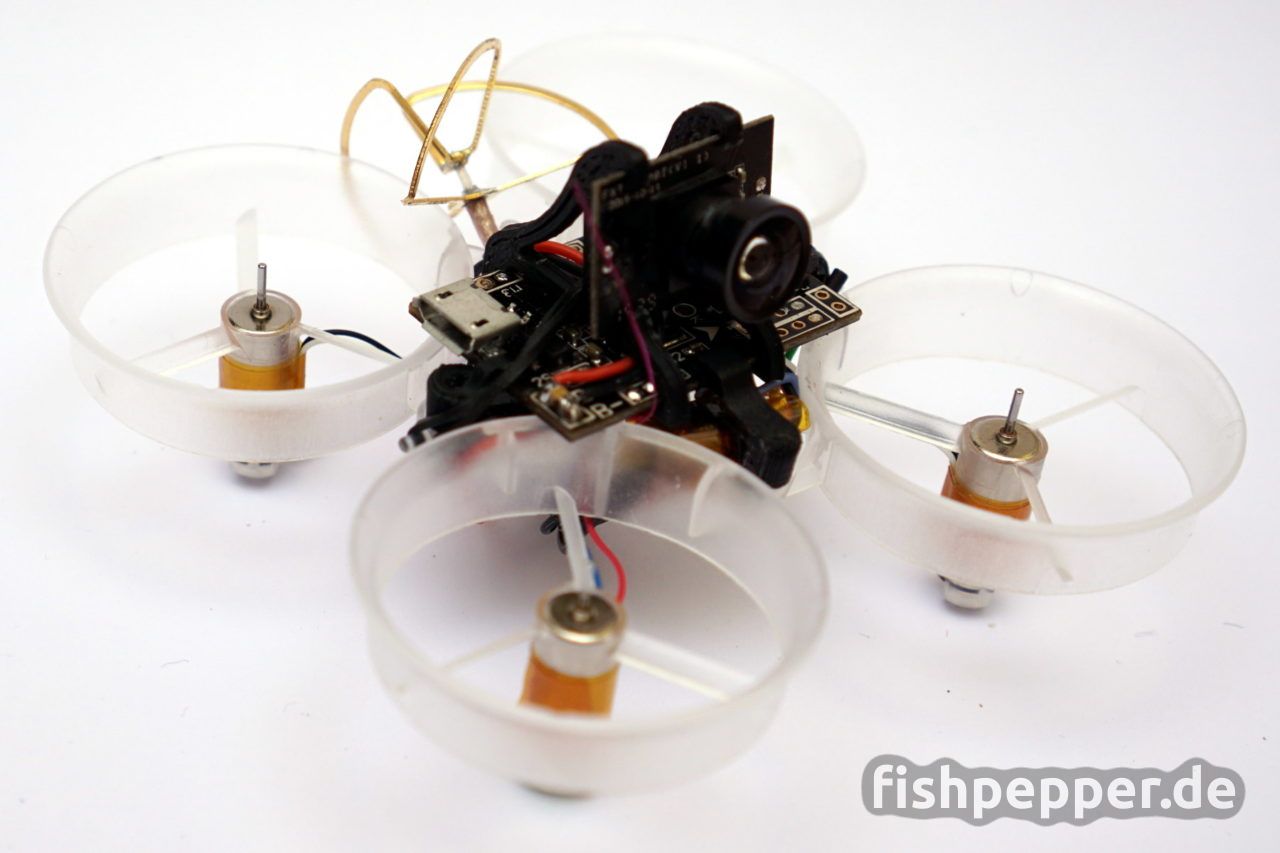
Software setup
Now it is time for the software configuration. The first settings can be done with no battery connected, the flight controller will be powered by the USB port. The battery is only needed once we want to spin the motors.
Flashing betaflight
The stock firmware on the board is cleanfligh (1.13). As i fly betaflight on all my other quads i am going to use this here as well. Have a look at my blog post how to flash betaflight 2.9.1 to this board. Once the firmware is flashed we can continue to configure this board. The next steps will guide you through the setup procedure for a brushed setup. As it is easier to replicate i will post the CLI setup commands here. You can apply these settings by clicking on the CLI Tab in the configurator. Please note that the settings will only be stored after you entered save in the command line. You can skip these steps and scroll down to my configuration file and apply all my settings at once.
Board orientation
As we mounted the board in a non-standard way, we will have to tell the flight controller about it. The board is oriented -90° on the yaw axis. Therefore we enter the following commands in the CLI window:
align_gyro = DEFAULT
align_acc = DEFAULT
align_mag = DEFAULT
align_board_roll = 0
align_board_pitch = 0
align_board_yaw = -90
save
Looprate & PID settings
I run my TinyWhoop with a 2khz gyro and pid rate while using the float PID controller.
set gyro_sync_denom = 4    # 2kHz Gyro rate
set pid_process_denom = 1  # 2kHz PID rate
set pid_controller = FLOAT # use float pid controller
# pid settings:
set p_pitch = 50
set i_pitch = 40
set d_pitch = 18
set p_roll = 45
set i_roll = 40
set d_roll = 18
set p_yaw = 80
set i_yaw = 45
set d_yaw = 20
set p_alt = 50
set i_alt = 0
set d_alt = 0
set p_level = 50
set i_level = 50
set d_level = 100
set p_vel = 55
set i_vel = 55
set d_vel = 75
Failsafe
Now it is time to set up the failsafe behavior. When we loose the connection to the transmitter we want the quadcopter to disable the motors and to “crash”. This is safer as the default “land” behavior. Our quadcopter is so light and easily affected by wind that we risk a flyaway in windy conditions with that feature. The following commands will set up our failsafe behavior:
failsafe_delay = 10
failsafe_off_delay = 10
failsafe_throttle = 1000
failsafe_kill_switch = OFF
failsafe_throttle_low_delay = 100
failsafe_procedure = ON
save
Port & Receiver setup
In my setup i use my custom, tiny FrSky RX with a SBUS connection and hub telemetry enabled. If you use something different you might have to modify this step to your needs.
# serial port setup for sbus frsky w hub telemetry:
serial 20 1 115200 57600 0 115200   #msp over usb
serial 0 1 115200 57600 9600 115200 #msp
serial 1 4 115200 57600 9600 115200 #hub telemetry
serial 2 64 115200 57600 0 115200   #sbus
# setup receiver
feature RX_SERIAL
feature TELEMETRY
set serialrx_provider = SBUS
set sbus_inversion = ON
set telemetry_inversion = ON
save #will reboot now...
Brushed setup
As this build uses brushed motors instead of brushless motors and an ESC we will have to set some extra configuration options. Basically we tell the flightcontroller not to send “ESC commands” but to send raw PWM signals for the attached motor. You can read more about this topic in my blog post that explains how to configure betaflight for a brushed setup.
set motor_pwm_rate=32000  #this will set pwm frequency to 32kHz
set max_throttle=2000     #brushed boards will use 0-2000 as throttle
set min_command=1000      #just to make sure min_cmd is not misconfigured
set fast_pwm_protocol=OFF #disable oneshot125
feature motor_stop        #motors stopped when not armed
#this should be adjusted to your motors:
set min_throttle 1060     #the throttle when all motors start to spin
save #will reboot now...
Mixer setup
As written before our motor setup is not as betaflight expects it to be. The motor rotations are swapped and we connected the motors in a different order. The following settings will correct that and tell betaflight how to control the motors according to the physical setup.
# mixer, different motor config and inverse rotation
mixer custom
mmix reset
mmix 0 1 -1.0 -1.0 -1
mmix 1 1 1.0 -1.0 1
mmix 2 1 -1.0 1.0 1
mmix 3 1 1.0 1.0 -1
save #will reboot now...
Voltage & current sensor
As i fly all my quadcopters with on board telemetry i wanted my TinyWhoop to have that as well. The F3 flight controller has a voltage divider on board, the voltage reading worked out of the box (and needed only a slight adjustment). Unfortuanetely there is no current sensor on my build, luckily it is possible to get a current estimation by using a virtual current sensor in betaflight.
Summing up
Now you should be done with the basic setup. My TinyWhoop flies extremely well with the stock PID settings. I uploaded a dump of my settings for my TinyWhoop F3 here. Open this file in a text editor, select all, copy the text and enter it into the CLI console. This should copy my setup onto your board. Enjoy & happy flying!
how do i do stuff like you do, i got inspired at your attitude, like taking it cool eventhought r**erstar cloned your fc without giving you credits, one question here how do i learn all the stuff you learnt?Tnx for the help. 🙂
Thanks! Just start small and keep going! Nowadays it’s cheap and easy to get information on the web. When I was a kid it was hard to get hands on (cheap) electronics… If I would have had access to all the goods china when I was a kid :-X Just keep on trying and learn along the way.
I’m using your PID settings for my off-the-shelf Eachine E010S (with bigger and heavyer batteries). They work great! Thanks a lot for this detailed description, it was a good read and I’ll see what I modify on my E010S.
Cheers, Manuel
Hi!
Great project!
How long does it stay in the air?
Best regards
I get around 3 minutes of real flight time at 25g AUW including the 200mAh battery.