Merry belayed Christmas and a happy new year everyone. I know, I am running a tiny bit late. My original plan was to release the tinyOSD and tinyFINITY sources ready for Christmas but then the usual things got into the way and I had to postpone this post. But here it is: I am releasing my sources of my custom full graphic OSD with insane update rates to the world. But that’s not all! I am also releasing a custom 16x16mm VTX design that includes all the hardware to run the tinyOSD firmware on it. But let’s step back and let me tell you what this is all about. But be warned, this is going to be a very long post…
The basic idea
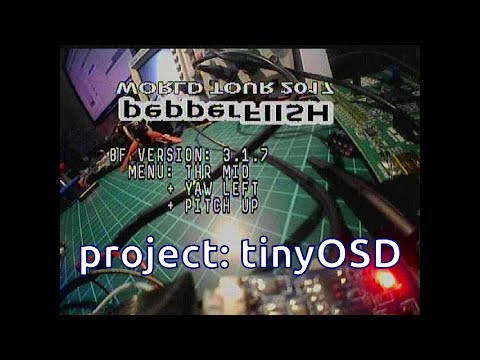
Some time ago I got annoyed by the available OSD solutions and I started to look for alternatives. Nowadays small micro controllers are fast enough and include fancy features like DMA so that the OSD generation can be handled in software. I selected a STM32F3 due to the availability in small packages and the necessary features I needed and got working. In May 2017 I posted a first preview of my tinyOSD development on my blog. That time it was running on a tiny PCB and was meant to be inserted between your camera and video transmitter. I got up to a point where I had integrated full communication into a modified betaflight firmware and could do all kinds of fancy animations:
As I like fully integrated solutions I started to work on a new PCB design that includes a RTC6705 video transmitter and my tinyOSD into one tiny 16x16mm board called tinyFINITY. The image shows a preliminary version where I tested a surface mounted ceramic antenna instead of the usual wire or whip-antenna (which was rejected in later designs because of the poor performance): 
But why?
You might be asking why all this effort? Well… I did not like the solutions on the market. At the time of development most OSD used the MAX7456 chipset to overlay a crippled B/W image on top of the video feed. This quite old chipset draws 120mA of current and gets glowing hot. For reference, my implementation draws 10mA under full load…
So what does my tinyOSD firmware stack give you?
- Fully opensource
- Very high update rates
- Full graphic overlays and animations
- Custom, nice font (can be changed)
- Currently showing 35 chars in 13 lines
- “Multi-color”: up to eight levels of gray on the screen
- Configurable global brightness and “blackness” setting
Most of the OSD firmware and tinyFINITY hardware is done. In order to integrate the OSD into your betaflight FC stack you need some kind of communication between the FC and my OSD. I tried to establish an open source communication protocol for camera and OSD stuff (openTCO) and worked on integration into betaflight. Unfortunately, complexity exploded and was too much to be handled as a hobby project. I had to work on the tinyOSD/tinyFINITY hardware, the firmware, the communication protocol, integration into betaflight, and last but not least, the betaflight configurator. My OSD offered so many features that I had to patch betaflight in so many places that integration into the betaflight master tree got more and more complex. This is just a hobby project I do mainly for fun and learning new things along the way. I do not have unlimited time resources and as you might guess, there are more important things in life such as hunting for food (my day job), my family, and such interesting things as household duties. Long story short I could not keep up with that many open issues and the tinyOSD and tinyFINITY sources remained unseen from the public in my private github repositories.
Opensource to the rescue!
But that is about to change! In this post I will release all my sources of tinyOSD and the tinyFINITY hardware to the public. But wait, there is a catch! Even though the firmware is mostly done and I have had a custom, patched betaflight firmware that could communicate with my stack this is not yet completely working. There is still work to be done which I can (currently) not do due to time constraints. But I open up my work to the public so that others can learn from it or maybe finish it. Also keep in mind that the tinyFINITY hardware is not fully tested and might contain bugs.
To my CHINESE COPYCAT friends: This is not finished. DO NOT steal it (yet)!
Sorry that had to be inserted, I have some experience with chinese companies selling my opensource work as theirs 🙁 Ok, back to the topic…
But how does it work?
You might ask why there was/is no other opensource OSD yet? Well, in principle the OSD stuff is easy: Take the analog PAL/NTSC video stream, detect the start of a new image and every image line start and overlay your data. Add some simple character rendering on top of that and you have your OSD. Well, now things get complicated… Analog video is, as the name suggest, an analog signal. Your microcontroller is digital and there is no way to digitize the image, overlay the data and recreate an analog video with those tiny microcontrollers that you want to have on your mini quad. You would need a faster analog digital converter, a LOT of memory and a much faster CPU. Be warned, it is now getting technical…
The common analog PAL or NTSC video signal encodes all kind of signal information into different voltage levels. A good overview can be found e.g. in this link. The line and frame sync signals are usually encoded as values below the “black” voltage level and are usually negative. Most (or all?) of the small CMOS and CCD cameras used in the quadcopter hobby do not stick to this standard, usually the black voltage level is around 0.3V and the sync is just around 0V.
Line detection
The first task is to detect the start of an image and the start of every line. Sampling the whole signal with the on-board ADC and looking for the sync signal will not work out, it’s just too much data. Lucky for us some clever people invented the so called analog comparator. It has basically two inputs and uses an analog comparator to compare both inputs. If one gets bigger that the other one it will raise a flag and tell the CPU that something important happened. This interrupt flag tells the CPU to stop doing what is currently in its pipeline and start to work on a so called interrupt handler. In order to use this to detect the start of a line we will have to connect the video feed to one input and a threshold voltage that we want to use to compare against on the second input. In order to be flexible and to be able to adapt to all kinds of cameras we connect the onboard digital to analog converter to this pin. This way we can set and fine tune the detection threshold in software by using video_io_set_level_mv() -- nice to have!
Data overlay
Ok, we can now detect the start of lines. But how can we overlay video data? Lucky for us there are some nice chips that can switch between multiple analog signals. We will “abuse” one of those to create our video overlay. First, we need at least two different voltages: one for “white” and one for “black” overlays. In principle only white would do but we want to draw black borders around text so that it stays visible in front of bright regions. As I like doing things properly we can also add multiple grey levels and by using two resistor ladder based digital analog converters we can control the brightness levels e.g. by calling video_io_set_white_level(). If we switch between the video signal, the “black” voltage, and the “white” voltage at the correct time we can overlay a custom gray value at any point of the image.
DMA & Interrupts
That’s where things get tricky. After detecting the start of a line you will have to switch to our signal at the right time. Any jitter in the time between start of the line and the final switching command will be visible as wobbly, unstable image. Unfortunately switching to an Interrupt handler is not instant and can vary some cpu cycles. The straightforward interrupt based approach produces very crappy images. Lucky for us modern CPUs such as the STM32F3 has DMA features and can be set up that a triggered analog comparator can instantly trigger a pre-configured DMA handler. And again, this handler will transfer memory data to a given peripheral. In our case to the SPI controller. The SPI controller will then output the data on its own with no CPU being involved. In order to send black and white pixel data we will simply use both SPI controllers. Again, this needs some tricky timing setups to make sure both output data in sync to each other. See video_spi_dma.c for details. Note that some CPUs feature a quad-SPI controller that could handle this on its own but those chips are to bulky.
Data rendering
With that working it is time to prepare the data. Once the DMA finished outputting a line it will have to be reconfigured for the next line. Lucky for us all we have to do is to buffer two video lines in memory: One is being transferred to the screen and the other one is filled with new data during that period. As the DMA controller takes care of filling the SPI buffers we are free to use the CPU to calculate the data for line n+1 while line n is being rendered on screen. Easy. (Once you get the timing right)
That being said all rendering has to be done online. Text, graphics and any gui elements such as bars or lines have to be rendered for every line. There is simply no way to keep a full video frame in the small memory of our CPU. But most of that is easy. Animations are a bit tricky but also possible.
Fonts
The main job of the OSD is to overlay text onto the screen. TinyOSD allows to display 35 characters in 11 lines (less for NTSC) over the video. I was browsing the web for a nice font. I found a very nice font made and published by Ste Pickford. I modified it a bit to be mono and added some missing special characters. The result can be found in src/font.h:
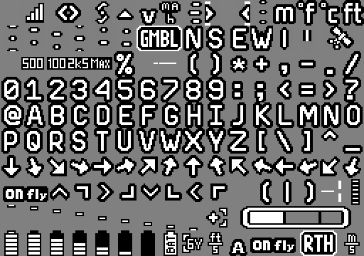 For now this is the default font. There are some helper scripts that can be used to convert fonts to the right header format (e.g. font_png_to_h.py).
Communication
The de facto standard for FPV OSD devices uses the MAX7546 chipset. The FC CPU uses a SPI bus and a very simple interface to talk to this chip. In fact you can not do much, change some settings, upload a custom font, and overlay a predefined grid of up to 30x16 characters on top of a PAL oder NTSC video stream. The tinyOSD lets you do much more, for example you can show custom animations, use multiple levels of brigthness, … In addition I want to have the highest update rates possible. This requires some wise protocol decisions and tight integration into the betaflight software stack. Most of it is straightforward but takes a lot of time. This is probably the part that will require most of the work.
Bonus: A versatile Crypto Bootloader
As time of development I was annoyed by chinese clones of my work that lacked proper credit. This is why I worked out a special bootloader that can be used to distribute and flash AES encrypted updates. The basic idea was to have the bootloader initially factory programmed. This image would contain an encryption key acting similar to a license file. Further firmware updates could then be released to the public without being useful to any party that does not know the initially flashed key. The operating principle is actually quite simple: On reset the bootloader will check the flash signature of the application space. If valid, it will jump into the application. If not, it will await an update. If an update is sent, the firmware stores the AES encrypted data in flash. Once the upload finished, some checks are done and then the firmware is decrypted in place. After this is done the bootloader verifies the application firmware and jumps to the new application. The tricky part are all the details…
Of course this “magic” is not necessary for an opensource application and open hardware. I was thinking of keeping the tinyOSD sources closed and sell licenses for the first year as I did with my tinyPEPPER 2 ESC. But it turned out to be too complicated to be worth the effort and as you might know I like the idea of open and accessible soft- and hard-ware. I decided to keep the bootloader in this firmware release as it might be useful to somebody.
Enough said, show me the sources!
Ok, as mentioned before this is not yet finished! If you want to actually go out and have some fun flying with your copter or you want to win a race this is not (yet) for you 😉 Let the developers do their thing and maybe this will find a way in a ready to use product in the future.
As mentioned before this project is based on two parts: Hard- and Software. The hardware details can be found in my tinyFINITY github repository:
https://github.com/fishpepper/tinyFINITY
I also uploaded the latest PCB revision to OSHPark, you can find this revision 0.3 here. The stepdown regulator part of this design was not tested yet as I powered it externally during the last testing phases.
In order to make this board do something you will need the tinyOSD firmware. Lucky for you (and all chinese copycats) this is also available for free on my github repository:
https://github.com/fishpepper/tinyOSD
Please give proper credit if you build a product out of this, I spend many evenings on hacking this thing together and that’s all I expect in return.
I will prepare some more documentations and howtos when the time permits. But this might take some more time as I am busy with a lot of other stuff right now. Happy hacking and enjoy!
TPS62153A seems to be only step-down converter. Is 1S supported?
Which camera are u using?
Quick question please Simon.
Is this large symbol for the processor the one that you used in your schematic please?
https://imgur.com/a/T7j0eaE
When I clone your repo I get errors about libraries and Kicad just uses what it thinks is best. It just look weird seeing as it is so large.
I did call git submodule init & git submodule update as well and also tried git clone –recurse-submodules.
Thanks
Yes, it is the processor. Strange that the submodule init does not work?!
Hi nice project. I would be interessed in helping.
some questions thought, what communication protocol do you think using for comm between bf and osd?
Will take a look at the source when I have a little time. It would be cool to have for my fc ^^
Great to see you back doing some more projects Simon. I have successfully built the tinyFISH and have all the parts for the TinyPEPPER2 but still have to find time to do that one. Sad that you have to warn off the Chinese Copy Cats but that is the reality in today’s Open Source world. I hope that that give you some due recognition this time.