 As you might have read I recently started to document the assembly of Benjamin Vedders insane 12S 50A (240A peak) motor controller called VESC. This is the fourth post in this series. In the previous VESC article I showed you how to assemble and solder the PCB on your own. Now it is time to do the initial flashing of the firmware.
This tutorial is meant for the VESC revision 4.12. There have been some recent changes on the software side. Benjamin Vedder started a new Website vesc-project.com where he is exclusively publishing the newest version of his graphical user interface. This new Software is called vesc-tool, the old (opensource) version was called bldc-tool. We are going to use the newer version as the old one does no longer support the most recent firmware. You will have to register at the project website and “buy” the free edition for $0. You will get an email and a download link within seconds so this is quite easy. Even though this seems a bit uncomfortable and I would really love to see this being opensource I can understand him for doing so. As you might know I made some experience with chinese copycats and missing credits in the past which made me sad.
Firmware
Lucky for us the microcontroller firmware is still open source. If you want to skip downloading and compiling the bootloader and firmware from sources I prepared an all-in-one hex file for you. You can download this file here and skip to the flashing section of this post. If you want to build it on your own, the following might be interesting for you. Let’s start by checking out the github repository and building the firmware:
git clone https://github.com/vedderb/bldc.git
cd bldc
Now we will have to configure the firmware for our board, change the settings to out board revision by editing conf_general.h:
#define HW_VERSION_410 // Also for 4.11 and 4.12
//#define HW_VERSION_60
Make sure to have the latest arm gcc installed and run make to build the firmware:
make build/BLDC_4_ChibiOS.hex
This should build and create the hex file. Next, checkout and build the bootloader sources:
git clone https://github.com/vedderb/bldc-bootloader.git
cd bldc-bootloader
make
This should also build and you will have all you need.
Flashing
Flashing an stm32 is quite straightforward if you are used to it and have the required tools. You will need a st-link or similar debugger/programmer hardware. You can find $2 clones of the st-link on aliexpress. As there is not much complicated stuff going on these devices always work quite well. You can also modify and use a stm32 evaluation board as most of them come with an included st-link programmer. Some (all?) will require to remove a solder bridge to free the RST line and jumper reconfiguration. This tutorial is written for the ST-Link.
Before we start with programming it is time for the initial power up of the VESC pcb. Take a current limited lab power supply and set it to 12V and around 0.3A. In case you have some solder shorts or broken parts this will save your day. If the current limit trips you should check your wiring. The board should not draw any large amount of current in idle mode. If all is fine you can proceed with flashing.
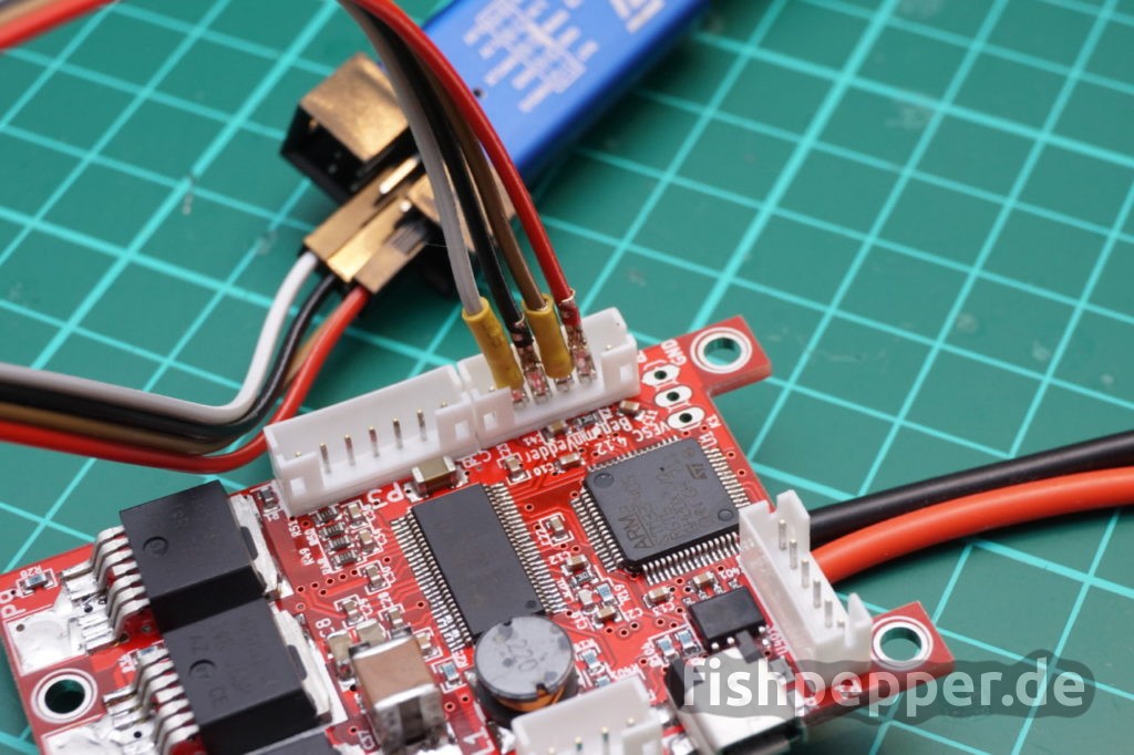
In order to program the stm32 chip you will need to connect the following signals to your programmer: RST, SWDIO, SWCLK, and GND:
The cables that come shipped with your st-link will not fit the pitch of the VESC JST header. As this is only used once for the initial programming you can hack your way by removing the black plastic shell and adding a heat shrink tubing to every second cable to make them fit to the JST header. The red wire connects to RST, brown connects to SWDIO, black connects to GND, and white connects to SWCLK. And yes, RST is really needed on the STM32F4. I have used STM32F3 in the past and only used GND, SWDIO, and SWDCLK but I got errors during flashing when I tried it without the RST line.
If you downloaded my all-in-one zip file the flashing is quite easy, unzip the hex file and rum:
st-flash --format ihex write BLDC_4_BL_AND_MAIN_MERGED.hex
After the upload and verify is successfully done, add a USB cable and power cycle the VESC. You should see a new USB device popping up.
If you compiled the source on your own you can enter the bldc folder and run make upload. When this suceeds you can flash the bootloader from the bootloader directory calling make upload as well. The order should not matter, however it is recommended to flash the bldc app before the bootloader.
VESC-tool
Now it is time to fire up the VESC-tool and see if it detects your brand new VESC. If you run linux it might give you some warnings about a running modem manager and wrong right settings. It offers you to fix it, just let VESC do it’s job by clicking OK. You should be able to connect to your VESC now.
That’s it for now, the setup tutorial will follow soon!
You can find previous and newer VESC articles here:
- Tutorial: Initial flashing a new born VESC (10/31/2017)
- Tutorial: VESC assembly — A tale of PCBs, stencils, solderpaste, and damned hot air (9/24/2017)
- VESC / DIY: How to cut SMD solderpaste stencils yourself using a Silhouette craft plotter (9/17/2017)
- 3S, 4S, 5S, 6S ?? — nah… Let’s go 12S/50A (240A Peak)! (9/12/2017)

