 If you have read my previous tutorial on how to measure the KV rating of a brushless motor you might be still wondering why you should ever need to do KV measurements on your own. Most of the time the manufacturer should list the KV rating and there is no reason for them to give you a fake rating.
I am planning to do some thrust and efficiency tests in the near feature and I need some special KV versions of the good old Racerstar BR1103B motor that you can not yet (?) buy. The stock motor comes in 8000 KV and 10000 KV, my goal is to add a 4500 KV and 6500 KV variant to this lineup by rewinding a stock motor. Even though this tutorial is based on the BR1103B, the basic steps for motor rewinding are the same for all outrunner brushless motors.
The basics
Before starting with the tutorial I want to give a short overview on the parts of an outrunner brushless motor. The following picture shows the main components I am going to talk about in this post:
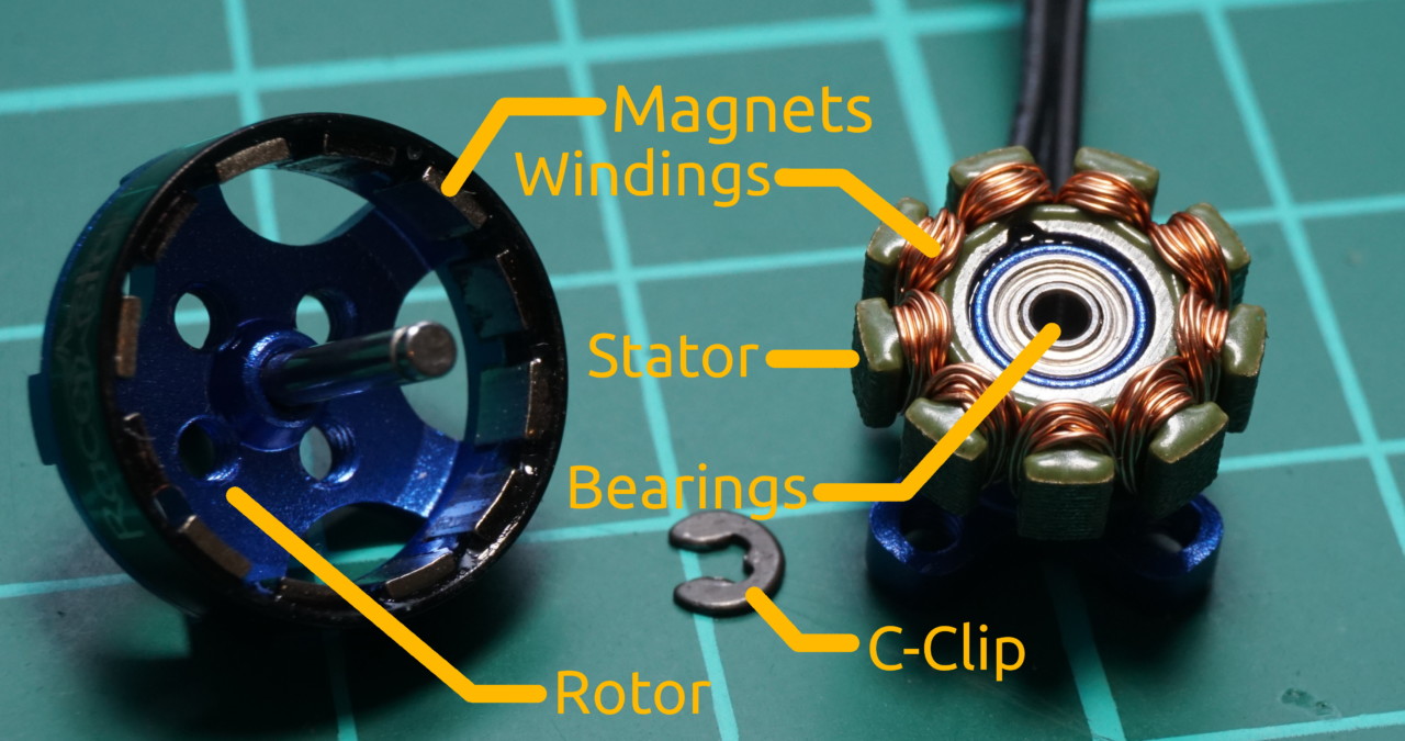
During motor operation the axis of the rotor, shown on the left, is held in place by a c-clip, lock screw or a similar fastener. The stator is made of thin metal sheets and several windings of copper wire form electromagnets that can create magnetic fields that can be controlled by your ESC. For three phase brushless motors, the number of stator poles is always a multiple of three. In the case of the BR1103B you can count nine stator shoes. The number of magnets in the rotor can vary. There are some popular combinations that are used the most. In this case there are twelve magnets mounted in the rotor which results in a popular 9N12P configuration.
As the name suggest, a three phase motor has three motor phases and you usually connect it to the speed controller with three wires. The windings on such a motor are made out of three long wires, wound in a special configuration around multiple shoes. There are two possible ways to connect the six endings of those three winding wires:
This motor uses the so called Wye or Star termination scheme: The starting ends of three coils are connected together and form a neutral point. The motors used in RC applications typically does not have this connection lead to the outside and a heatshrink makes sure it does not create a short circuit. The other termination scheme is called Delta termination. The three pairs of two coils are connected together and routed to the outside. There is no physical neutral point available.
Delta terminated motors spin 1.7 times faster than a Wye termination whereas a Wye terminated motor has 1.7 times the torque of a Delta terminated motor. It is possible to convert a motor from Delta and Wye and vice versa by changing the solder connections and scheme of the coils.
Unwinding
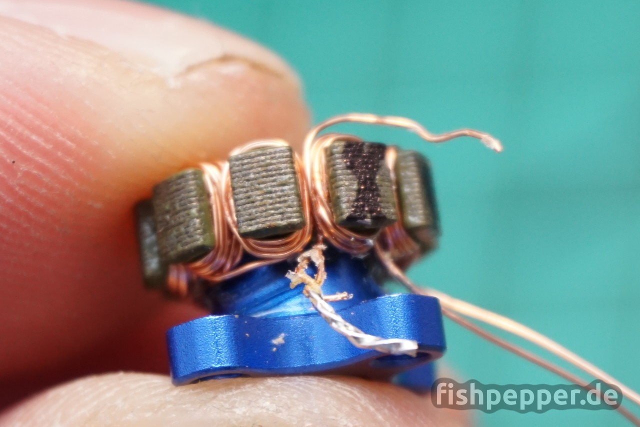
Most likely you will start with a motor that is already wound and you will apply the same winding scheme. Start the disassembly by removing the C-Clip and lift of the rotor. Some people recommend not to leave the rotor without a stator for longer periods of time, the magnetic field lines will not be closed and the magnetization can degrade. I could not find a scientific reference on that (if you do please let me know!) but it might be a good idea to do so. I use a burned old stator for that purpose. For the Racerstar BR1103B the best part for the start of unwinding is the star point junction. Remove any heat shrink and gently untwist the connection.

Remove the solder joint by cutting the wires using a sharp cutting plier and start by unwinding the first coil. Depending on how the coils were secured it helps to apply some heat to soften any glue.
Make sure to take notes on the number of windings, the orientation and the order how the coils. Two wires and two thirds of the stator coils have been removed, only one left.

Once finished use your notes to create the winding scheme. The following picture shows my notes on the winding scheme if the BR1003B:

This motor uses the most basic winding scheme (ABCABCABC) and a Star termination. Every set of the three coils made from one single wire is evenly spaced and wound onto every third shoe. Motor winding patterns are not always that simple, if you are curious, some examples of more complex winding patterns can be found in this link (the BR1103B corresponds to “CD-ROM”).
In addition to the winding pattern you will have to count the number of turns. I can really recommend counting in half-turns. Even though it sounds like a very very basic task, on the one hand counting correctly in full turns is remarkably hard and on the other hand there are motors that use n + one half turn for the coils. I ended up counting 20 half turns or 10 full turns for the BR1103B in 8000KV.
Now it is time to figure out the thickness of the used enamel wire which is quite hard to do properly. Take multiple readings and take the average. I would assume that the outer diameter of the wire used in the BR1103B 8000KV is 0.18 mm. For simplicity I assume the coating is 0.01mm thick. Please note that some sellers of enamel wire give you the outer diameter including the isolation coating and some give you the OD of the plain copper wire. Good sellers will give you both. Make sure to order the correct thickness. It took me some time to find a good seller that sells small quantities in Europe (see this link).
Before you can start to rewind the motor most likely you will have to remove some remaining glue from the stator. Apply some heat (80-100°C) with a hot air gun and use a soft material like wood or plastic to scrape it away. Do not use anything sharp or metal utilities to remove the glue, you do not want to damage the green isolation paint from the sharp stator edges.

Calculations
Now it is time to calculate the number of turns you want to apply. As stated before my goals is to get around 4500 KV and 6500 KV. The main motor used 10 turns for 8000 KV. So let’s do some math. You can use the following formula to calculate the expected KV value:

e.g. for 11 turns instead of 10:

The following table shows the (rounded) expected KV values for a given number of turns:
| # of turns | Expected KV |
| 10 | 8000 KV |
| 11 | 7300 KV |
| 12 | 6700 KV |
| 13 | 6200 KV |
| 14 | 5700 KV |
| 15 | 5300 KV |
| 16 | 5000 KV |
| 17 | 4700 KV |
| 18 | 4400 KV |
| 19 | 4200 KV |
| 20 | 4000 KV |
I will use 12 turns for 6700KV and 17 turns for 4700 KV.
Now it is time to decide which wire thickness to use. In general you want the wire to be as thick as possible. However you are limited by the number of space between the stator shoes. You can throw some math onto that problem but I prefer the simplicity of just giving it a try. I ordered a whole collection of different wire from 0.1 mm to 0.2 mm outer diameter in 0.01mm steps. You do not need much, 1.5m should do for a single motor. You can also use multiple strands in parallel to achieve a better fill grade and get a combined wire thickness that you do not have. Don’t be fooled by the difference between wire thickness and area. For example a plain copper wire of 0.18mm has an area of 0.0254 mm² . A single wire of 0.1mm has an area of 0.008 mm². If you take two 0.1 mm wires in parallel you end up with two times of that value which is 0.016 mm². You might be tempted to think “oh, thats twice 0.1mm, should be better than one 0.18mm wire”. But this is way less than one 0.18 mm wire and behaves more like one 0.15 mm wire (which has 0.018 mm²).
I managed to squeeze 12 turns of the original 0.18 mm (including isolation) wire onto the shoes. So I will use that for the 12T version. We need to use a significant thinner wire for the 17T version. Which is ok as the consumed current will also be reduced for higher turn and lower KV motors. The sweet spot seems to be around 0.16 mm wire (0.02 mm² instead of 0.025 mm²). You might be able to squeeze 0.17 mm wire onto it as well but I did not investigate into that further as the seller where I bought my wires did not have it in stock.
Rewinding
Once you have decided the number of turns and the thickness of the wire you are all set. Remove the C-clip and lift of the rotor. Place it onto a spare stator to avoid a degradation in magnetization.
Next, cut three pieces of your wire, each 50 cm long. Start by winding the first set of three windings. Again, it helps a lot to count in half turns. That way it is harder to make mistakes, trust me. You really want all your windings to have the very exact number of turns!
Just take your time. Do not worry, the first three windings are the hardest, you will get faster the more you wind. Make sure that the first windings are pushed and seated properly into the slot. Once the first set is finished add a note (e.g. a knot) to the ending side of the wire you just wound and proceed to the next set of three coils:

Mark the end of this wire as well, I used to twist all ends together in preparation for the star point. Also make sure to fixate the windings you just have finished. I wrap the remaining wire of the fixed coils around the feet of the base during winding. Once that set is done as well proceed to the third set of three:

That’s it for winding. And please do not ask me how many times I redid this whole thing… I counted wrong, stripped the wire by pulling to much or the windings got loose during handling. The first one took ages to finish!
But once you are done with winding it is getting quite easy and relaxing. The first route leads to your wifes cosmetics cabinet. Locate and borrow some clear nail finish paint (reminder to myself: put it back into my wife’s cabinet once I am done. really! do not forget…). Take a needle and apply some drops of it to your new windings:

This will add some fixation that can be easily removed when needed. Now twist all three wire endings, cut them and solder them together. Use a lot of heat to burn away the coating. Double check for a good connection by using a multimeter between the soldered star point and all three open wires.

Now cut the remaining phase wires and apply solder as well.

Take some 30 or 32 AWG silicone wire and solder it to the phase wires.

Add two very thin heat shrinks to the outer two phase wires and cover all three wires with a combined heat shrink and use some nail finish to glue it in place. Add another thin heat shrink to the star connection as well.

Put the rotor back onto the stator and make sure not to forget the C-Clip as I did *cough* And that’s it. You just rewound your first brushless motor. You can now hook it up to a motor test stand or use other ways to verify the KV rating and proceed with the next three motors…
Have fun!
Hi fishpepper,
thank you very much for this tutorial. What I didn’t get is which wires have to soldered together. Could you please explain this in more detail?
MfG
HoNau
Have a look at the winding scheme:
https://fishpepper.de/wp-content/uploads/2017/10/winding_scheme.svg_-1-768×211.png
Usually you will use a star termination like shown in that picture. You will have to solder the three endings of the three “separate” coils together. This connection is not connected anywhere externally, just add a heat shrink over the solder joint.
The other three wires are the motor phases and those go to your ESC.
Hello ! There is a thing’s who i don’t understand…
to make a low kv, we need to make many turns ? So the wire will be thinker ?
If it’s thinker, it will have a bigger resistance and become hot more quickly ?
thank you for yours answers !
Lower KV = more turns. This means the wire gets longer and thinner (= more resistance per meter).
The higher resistance reduces the current (U = R * I -> I = U / R).
How hot it gets depends on a variety of factors (mechanical load, power input etc)
Awesome, I’m going to do it ! for reals this time!
Thanks for another great tutorial. Now I have a purpose for all of my burned out motors!
Nice write up. My first and only time I rewound a brushless motor was for the tail motor of a micro 100 Heli. 20 turns or so. Kept miscounting, getting distracted by family, etc. it was tough. Took me many days before success. Hah
I can’t imagine having to do it three more times because quadcopters uses 4 motors. LOL
Distracted by family – I know what you mean 🙂
Counting in half turns really helps. If one winding counting ends on the top instead of the bottom you know something went wrong *g*