
It feels like christmas is fast approaching this year… The days got quite short, trees are losing their leaves, and it is getting colder already. And now look what Santa Charles Blouin from RCbenchmark just sent me: Wohoooooooo… The postman, or rather the customs employee, handed over a 1580 dynamometer motor test stand to me! I will no longer get in trouble by gluing random metal brackets to my wife’s kitchen scale — great! Please note that Charles kindly provided the test stand for a review. I will do my best that this will have no influence on my opinion and I will do my best to write about the advantages and drawbacks of this device.
In case you have never heard about it before you might be ask what this thing is used for. The most basic functions of a device like this is to measure thrust of a motor/propeller combination. Of course that’s not all you can do, this device can measure much more variables, but more on this later. There are two different versions of the dynamometer that have different sets of features but run both on the same software stack and connect to your PC by using a standard USB connection.
1520 Series [datasheet]
This is the starter version which allows you to measure the most basic numbers of a motor propeller combination:
- Thrust ± 5 Kgf
- Voltage 0-35 V
- Current 0-40 A
- eRPM 0-190k via motor phase probe or (optional) optical probe
- Accelerometer on PCB (vibration level)
- Overall efficiency g/W [derived]
1580 Series [datasheet]
My review is based on the 1580 series. This kit features all that is listed above for the 1520 series plus the following additional features:
- Torque ± 1.5 Nm
- Motor winding resistance 0.003-240 Ω
- Accelerometer on PCB (vibration level)
- Motor efficiency % [derived]
- Propeller efficiency g/W [derived]
For me the most interesting part is that the addition of the load cells for torque measurements allow direct motor and propeller characterization. In addition, the measurement of vibration can be handy to see how balanced different prop types come from the factory. I think all micro brushless builders came along those [insert your favorite swearword here] propellers that are so unbalanced that they vibrate the lens out of your camera in flight (this really happened to me…). It is nice to get a quantitative measure for this.
Kit content
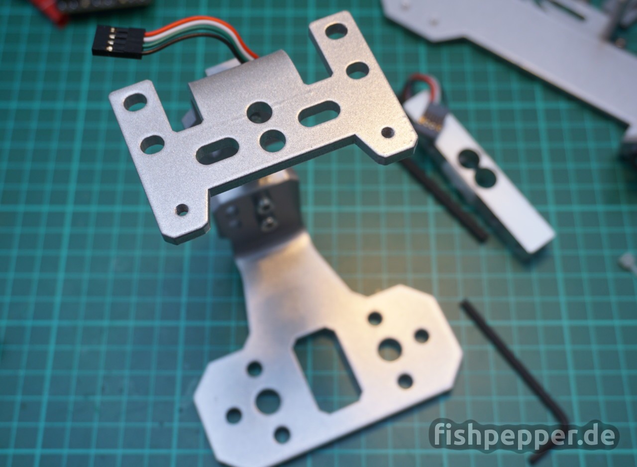
 This thing comes in a 26cm x 18cm x 11cm sized cardboard box and is well stuffed by foam. The box includes everything you will need for the assembly. Having the matching Allen keys in the set sped up the assembly by at least five minutes as I did not have to search for my personal set of Allen keys. Really nice to have it in the box!
- Test stand aluminum parts
- Two 2 Kg load cell for torque measurements
- A 5 Kg load cell for thrust measurement
- The black main PCB
- Heavy duty 12AWG and USB cables
- A 200g calibration weight (Dual use: assembly helper)
- A bag of screws, spacers, zip ties
- A set of three matching Allen keys
Before we start with the assembly, let’s have a short look at the heart of the dynamometer, the black PCB:

This board features a microcontroller, USB to serial adapter, and different amplifiers for the load cells, winding resistance, and the current sensor. There is an mini USB connector and various pin headers and connectors for additional sensors. It also features massive screw terminals which make ESC swapping a breeze. The PCB assembly is stated to be done locally in Canada and looks to be made at a high quality — nothing to complain. Enough time spent on dull facts, let’s get this thing up and running!
Documentation & Assembly
The dynamometer comes with a printed manual that features 14 pages that show assembly and installation instructions. All steps are shown at a good detail level with wire frame renderings of the parts used. I would rate this to be even easier to assemble than the mechanical frame of any quadcopter frame kit. The whole assembly took me less than 15 minutes:


RCbenchmark released some good tutorial videos on the assembly and on how to use the software (part 1 and part 2). I can really recommend watching those first. They give you a nice overview and makes the progress even easier.
Software
Once you finish the assembly part of the written manual it asks you to download the software. My printed version came with instructions to download the chrome app (link). As google is about to remove app support from chrome, RCbenchmark recently released a native desktop app as well. I am happy to see that this is still a cross platform application: It runs on Windows, Max and Linux. It is really a pitty to see app support fade away from chrome. The well known betaflight configurator is as a chrome app as well. It will be interesting to see what the betaflight community will come up with in the future. But back to the topic.
The following experience is based on the “old” chrome app version of the software. I downloaded and installed the chrome app, connected the board and clicked connect. Result: Connection failed. After checking for the obvious linux stumbling blocks like permission problems etc I could not find any problem on the PC side. In the end I tried to use the well known windows approach: Install it again. I went to the setup menu and clicked the firmware upgrade button. The software told me to unplug and replug the board and click upgrade again. And voilà: firmware flashing succeed and there were no more connection problems. I have no idea what was wrong in the first place but after those two clicks the board was ready to go. I reported the issue and they are investigating it.
Another bugger was that I forgot to set the working directory in the setup tab and there was no default set during startup. Make sure to set a valid directory, it seems like at least under Linux there is no default and I got an error message when I tried to use the automatic tests.
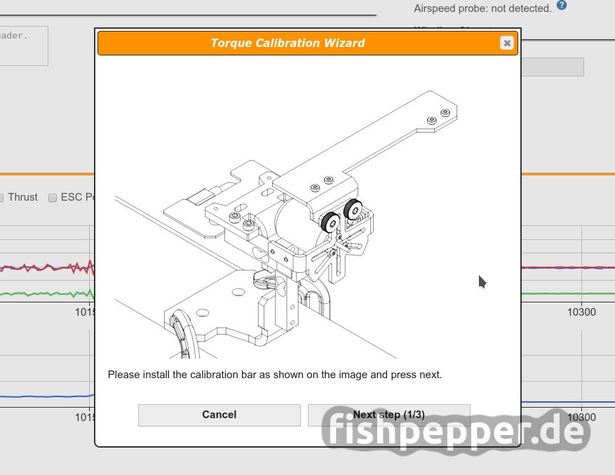
Calibration
The first thing you will have to do is to calibrate the load cells. Enter the Utilities sub menu and click on “Calibrate Thrust”. This will open a wizard that will guide you through the calibration procedure.


As this test stand does not yet support DSHOT, you will have to calibrate your ESC min/max settings before you can use it. In order to be able to hear the calibration beeps, I would recommend to have the motor connected (without propeller). Disconnect the ESC power cable and go to the manual control tab. Now tick the checkbox below the ESC slider and set the slider to the maximum (up). Connect the ESC power cable and wait for the calibration beep and move the slider to the lowest position. Once the beep confirms a successful calibration you can remove the tick on the checkbox and cut the power from the ESC.
First measurements
My initial test was to do a very basic measurement. Start by unplugging the ESC power and mount a propeller to your motor. Make sure the test stand is secured to your table. Connect the motor cables to the ESC and fix all wires using zip ties, you do not want to have loose cables interfering with your high rpm propellers, trust me… Once all parts are properly fixated it is a good time to click on “Tare load cells” in the main tab. This will tare all measurements and you are ready to go to take your first measurements.
Before we start with spinning the motor we will need to set up the electronic rpm probe. In order to measure the RPM of the motor we will connect the RPM probe to one of the motor phases. The test stand can use this wire to measure the electronic rpm of the motor. As the electronic field will rotate faster than the bell, the software needs to know the number of magnetic poles in order to calculate the real rpm. You can find this number in the motors datasheet or just by counting the number of magnets in the bell (e.g. 12 for the Racerstar BR1103B). Go to the setup tab and enter the correct number into the “Number of Poles” field.
Head over to the manual control tab. We will now spin the propeller so double check that nothing can collide with it. Make sure the slider is on minimum (down) and click on the checkbox. Now slowly ramp up the ESC slider. Your motor should start turning. You can activate different checkboxes for the real time plot and you can read the present thrust, rpm and current for your motor in the left sensor tab.
That was easy, now let’s try some of the automatic test scripts. We will let the test stand measure the motor Kv value next. Unplug the power and remove the propeller, the Kv value has to be measured under a no load condition. I would also recommend not using the maximum voltage rating of your motor. Running the motor at full throttle with no load will introduce significant stress to the bearings. By running this test at 3S instead of 4S the motor will be spinning at only 75% of the speed that it would reach on 4S. As the test stand does all calculations for you and also measures the battery voltage, it will of course calculate the proper Kv values no matter on what voltage you do the test. Head over to the Automatic control tab and load the “Measure Kv” script and run it. Your motor will now be spun up to the maximum speed and the script will measure and calculate the motor Kv rating. You can see the results in the “Console” text box:
> Started script: Measure KV.js
> Initializing ESC...
> Setting "esc" to 1000
> Waiting 4 seconds...done
> Ramping esc from 1000 to 2000 in 15s.
>   ramping 100.0%, val 2000
> Waiting to reach steady speed
> Waiting 4 seconds...done
> Reading and averaging next 100 readings...done
> Motor KV value 4536
This log shows all the single steps the Kv measurement test script executed. The motor was successfully tested and the tool measured a Kv value of 4536  .
.
Things I missed, suggestions & feedback
When I was using the test stand I noticed some room for improvement. I did sent the following suggestions to Charles:
DSHOT
It would be very nice to have DSHOT support integrated into the firmware. This way one could skip the ESC calibration and start right away. I also had some issues with the ESC not being ready after the 4s low throttle signal of the Kv test script. The good news are that they are already working on DSHOT support!
Silicon wire
I would prefer having 12AWG silicon wire as the main power cable. This might be my subjective personal preference as the normal cabling will certainly deliver the same performance. Charles told me they are looking into it, the next batches they do might contain silicon wires but no guarantee.
Micro-brushless / low thrust Edition
The dynamometer uses a 5 Kg load cell for thrust measurements. When I abuse my motors that I use for my micro builds I might get thrust in the range of 0.1 Kg. So my maximum thrust is like 2% of the measurement range… Whooops, you cant expect much resolution and accuracy at that level. However there is an easy fix: Update the load cells. It looks like you can get the exact load cells that are used for as low as 0.5Kg. However I could not find a seller on aliexpress for the 0.5 Kg version. I am going to use the 1 Kg load cell from this set from banggood. There are also some offers for this type on aliexpress. In case you have the 1580 dynamometer you can also replace the 2Kg load cells for the torque measurement. Just make sure to buy the right dimensions (80x10mm with 2xM4 and 2xM5 threads). Even though it is not a big deal to source the load cells from aliexpress, it would be handy if there would be a special edition or an add-on pack for low thrust measurements. Charles told me that this is on their todo list as well, but before that there will be the new 1780 series release. This will feature a whopping 25 Kg load cell. Check out their newest video testing the new beast — scary!
Chrome App or Desktop App?
It is really a pitty that google decided to fade out the support of chrome apps. I really liked the cross platform idea. The version of the printed assembly guide still referred/linked to the “old” chrome app. However there is also a new native desktop application that runs under windows, mac and linux as well. Charles told me that the printed manual will be updated soon to reflect this.
Working directory
As mentioned before it seems like the chrome app did not set a default path for the working directory under linux. When I tried to access the automatic tests I got an error message about a missing/invalid user directory. The fix is easy, I entered a valid directory in the setup tab. I suggested that the software should use something like /tmp per default. Charles added this on their todo list so it should be fixed soon.
Summary
The assembly, installation and software use are really enjoyable and even though there were some minor hiccups, the overall performance definitely matches what I expect from a device like this. At first the price point seems quite high but please remember that this is neither a big company that is producing this item nor this is produced one million times in China. And yes, you can manually measure thrust with a kitchen scale, current and voltage with a multimeter or hook up a manual test stand that you can buy. This will most likely do fine for some basic tests and should be enough if you do this once in a year for three propeller combinations. Been there, done that… But for automated testing for many propeller and motor combinations this thing just gets the job done much faster. A lot of work went into designing and fine tuning this thing and the software.
You might be asking if you should buy one of these, and if yes, which one? Well, from the short time I have spent with this device until now it looks really nice. From the feature set I would most likely go all in for the 1580 series if your wife purse allows it. Being able to measure efficiency, vibration levels and the winding resistance is really nice when you try to select components for a new copter design. However, in order to give my honest opinion, I am going to keep using this thing a few more weeks and write a summary on how the device turned out to support me along the way. I am about to write a series of micro brushless motor posts where I will use this device, those will be added to the bottom of this post once I get them online. I think this is in your interest to keep on reading the posts where I use this device and draw your own conclusions.
Please refer to this list of posts that are about the 1580 dynamometer:
- Thrust-Test: AOKFLY RV1106 4000KV (5/23/2018)
- Thrust-Test: Brotherhobby Returner R3 1106 5100KV (12/7/2017)
- Thrust-Test: DYS BE1104 6500KV (12/3/2017)
- Thrust-Test: Racerstar BR1103B 6000KV (rewound) (12/1/2017)
- Tutorial: Changing the load cell of a RCBenchmark 1580 Dynamometer from 5Kg to 1Kg (11/30/2017)
- Thrust-Test: EMAX RS1106 4500KV (11/29/2017)
- Thrust-Test: Racerstar BR1103B 4500KV (rewound) (11/23/2017)
- Thrust testing 110X motors — Time for the truth in numbers! (11/23/2017)
- Review: RCBenchmark Dynamometer 1580 — thrust testing and more (10/19/2017)
I am so curious for your results! Love these articles.