 This is a follow up post to my previous blog post on how to replace stiff wires on micro brushless motors such as the Racerstar BR1103B. Last time I cut and re-extended the wires outside of the motor. Encouraged by Sams blog comment I got ready to sacrifice one of the motors for science! To all the curious people: No, it did not end up on a landfill, it turned out beautifully!
But back to the topic, I have been building micro brushless quadcopters like my pepperFIISH for a while now. Over the last builds it became more and more clear that one of the weakest spots are actually the motor wires: Most of the small brushless motors come with stiff, single strand copper wires covered in heat shrink tubing. Most of the time this wire breaks due to vibration directly at the soldering spot at ESC pad. Often this is due to previous damage caused by minimal cuts occurring while stripping the isolation but it also happens to perfect solder joints.
The root of the problem is the single stranded and stiff wire. Replacing it with a flexible multi strand silicone cable helps a lot. In this tutorial I am going to show you how to replace these cables. This time the tutorial is not for the faint hearted, we are going to disassemble the bell, remove and cut the winding wires inside the innards of the motor. I am going to write this tutorial again based on a Racerstar BR1103B motor but in principle this can be applied to all motors. If you use bigger motors make sure to use the proper sized silicone wire. Measure the single stranded wire thickness and use this AWG chart to lookup the best matching AWG size. I measured the wires of the 8000KV BR1103B to be 0.22mm in diameter and the perfect match would be 31 AWG. This is not common and as thicker wires are generally better I choose 30AWG for this motor.
You will need the following items:
- Motors of your choice: Racerstar BR1103B
- a sharp (!) wire cutter: this one is a real bargain
- heat-shrink tubing: 1.0mm + 1.5mm from this set
- matching silicone wire: 30 AWG (this one is good, only 0.8mm OD)
- a soldering iron and some solder
- a hot air station helps a lot
- tweezer (this time you will really need it, trust me)
[1] Disassembly
The first thing you need to do is to remove the motor bell. There is a small C-Clip on the bottom of the motor. Lucky for us you do not need any fancy tools for removal, a thin sewing needle will do:

Make sure not to lose this small clip! Just in case you have spent the last half hour searching for it on your desk: have a look inside the motor bell, the clip is magnetic and i have heard *cough* that it might be hiding in there… Once the clip is removed you can pull out the motor bell:

[2] Remove the glue
The good news are that the glue is really weak and brittle. Remove the glue with a plier and cut the heat shrink tube. Be careful not to cut the wires. You can now slide back the isolation. With the wires exposed you can see that the “wire” is in fact nothing more than the winding wire covered in heatshrink…
[3] Cut and pre-tin the wire
Take the wire cutter and cut the wires roughly 8mm from the motor. Congratulations, you have now reached the point of no return — so let’s continue!

Now comes the important step: Ramp up your soldering station’s temperature to 400°C (!) The winding wire coating will burn away at this temperature. Apply some fresh solder to your soldering tip and hold the end of the wire into the solder blob. It should take less than two seconds and the coating is gone:
Make sure to lower the temperature once done, you do not want to solder with that setting… All flux will evaporate quickly and your solder job will look like a mess.
[4] Solder silicone wires
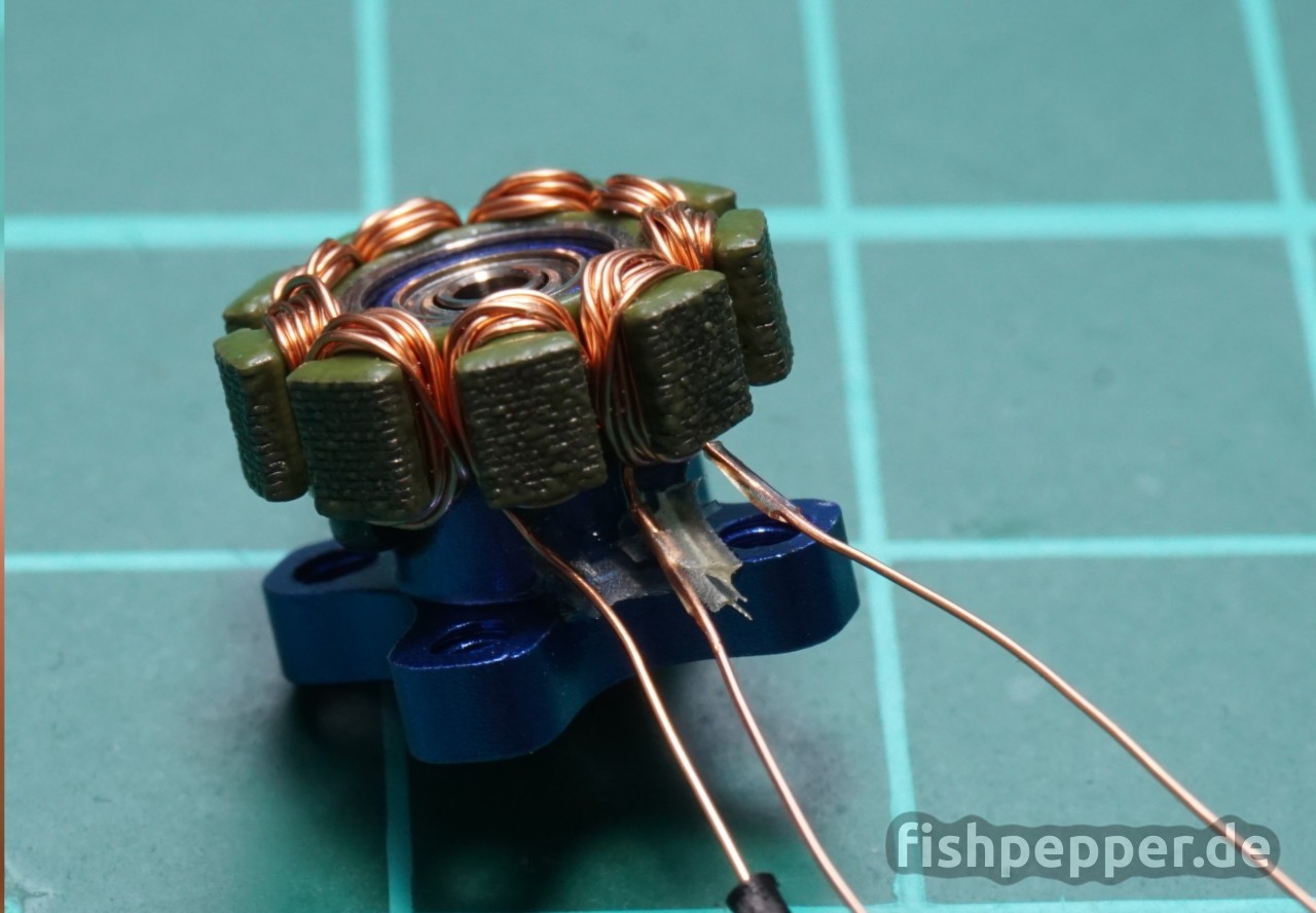
Now pre tin three silicone wire ends and solder them to the motor wires:

[5] Heat-Shrink
Cut two (!) 3-4mm long pieces of 1mm heat shrink tubing. Sleeve them over the outer wires. The center wire will stay exposed, the final heat shrink tubing that covers all wires will isolate that one:

Now re-align the wires close to each other using the tweezer. Take some 1.5 mm heat shring tubing and cut a 4mm long piece. Use the tweezer to widen it a bit so that the three wires fit into it. Sleeve it over all three wires, shrink it using heat, and immediately bend it into shape:

[6] Glue!
Now it is time to add some glue. Be careful and bend the heat shrink upwards, apply some 2K epoxy and bend it back down. You might want to add some epoxy on top of it as well.

[7] Assembly
Attach the bell to the motor and use the tweezer to put the c clip back on again:

That’s it! This one will hopefully last forever and not die on the first crash… Repeat this three times for the other motors and you are done! Or five if you are building a hexacopter 😉

Happy flying!
You think that 30awg is a reasonable match for 0.2mm core wire (as best I could measure) in 0703 motors? I can’t seem to find silicone stranded wire in 32.
30 AWG should do as well 😉 It’s just a bit thicker (30AWG = 0,255mm width, 32AWG = 0.202mm width)
Yes, as soon as I posted, I saw it in your list… 🙂
When you wrote “This is not common and as thicker wires are generally better I choose 32AWG for this motor.”, shouldn’t you had chosen 30AWG cable to go bigger ?
Thanks for spotting this. Of course I meant 30 AWG (as linked in the shoppping list). Corrected.