 This is a previous revision, please have a look at the more recent revision 0.5.
In this post I am going to share all the parts you need to build your own super tiny tinyPEPPER 4in1 Blheli_S ESC. All the following information applies to the current version 0.3 of tinyPEPPER (tagged as revision 0.3). If you are wondering what makes this thing so special, have a look at the main tinyPEPPER project page.
Circuit board
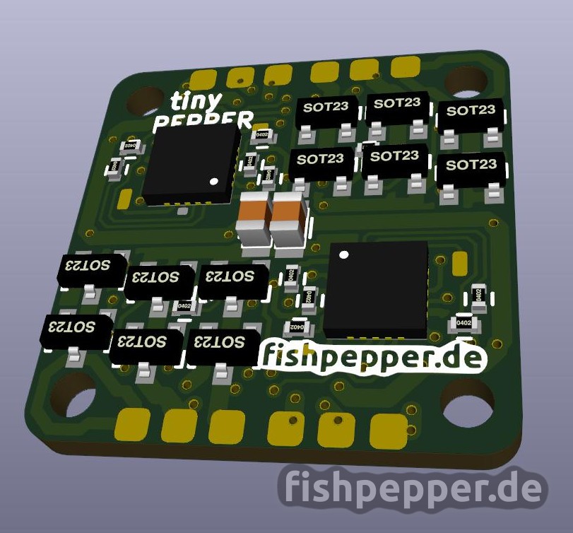
This board uses the same outer dimensions as my tinyFISH FC: 20x20mm with a hole-to-hole distance of 16mm (M2). When manufactured in 0.8mm FR4 the completely assembled board weights silly 1.2grams! This board requires some experience with SMD soldering and requires a hot air gun or a reflow oven.
BOM
You can find the bill of materials with part references and ordering numbers for farnell and mouser on this google doc sheet. Make sure to order genuine mosfets, the clones on aliexpress have a very poor quality (higher RDSon and bad thermal dissipation).
Design files
The design files are released under the CERN open hardware license v1.2. Before using the design files for commercial projects please make sure that you read and understand this license! You can use the files for your projects, just make sure to give proper credit (by e.g. linking to the tinyPEPPER ESC page). Additionally release all modifications you do and all work you derivate from this under the same license.
You can find the design in the kicad file format on my github repository. You will need a recent version from kicad. I compiled my own binaries from kicad commit hash #efdfaeb.
If you want to skip the hassle of rendering the gerber board files on your own you can simply skip this step and checkout and order the part from OSHPark.com using this Link (rev 0.3). They offer a really great quality for a ridiculous low price (it is $3 for three copies!). Make sure to order the 0.8mm and 2 Oz copper version.
Placement & Connections
You can use the following diagrams for the component placement. See my github repository for the full resolution files in SVG format.


Do it!
Now it is time to build your own! This page has all the information you need to build your own tinyPEPPER ESC. Sure, this required very fine pitch soldering, but if you have some experience with SMD soldering give it a try! If this sounds to complicated to you, do not worry, I am quite sure someone will pick this design up and sell it sooner or later.
If you have built any my stuff I would be happy to see and hear how it turned out for you — send me an email!
Thanks a lot, this is awesome.
I will definitely give myself a chance to reproduce such esc’s. I have been wondering for a long time how those BL-Heli ecs’s were wired up.
Now I know !
Tinyfish FC kicadfiles keep saying they where designed in a newer version of kicad. Pcbnew will not open.
You will have to compile a more recent kicad version for this. I did the design with the kicad commit hash efdfaeb.
If I understand correctly, instead of downloading kidcad, you use github to get the latest version using command line. Like these instructions?
http://docs.kicad-pcb.org/doxygen/md_Documentation_development_compiling.html
then you type in the #efdfaeb and I also don’t know what that means. You are the only person on the internet using that so I guest it’s releated to your github
my other question is regarding your parts library. All the mosfet, resistor are not in the schematic. I get the message that it’s suppose to be in the /kicad_misc/ and name custom.
Can you post the schematic in PDF for all your projects?
thanks again
In order build my kicad version you clone the kicad git repo and then you type
git checkout efdfaeb
Then you build it.
For the missing libs: Enter the tinypepper source and type
git submodule init
git submodule update
This will install my parts library to this source folder.
On the kicad download page you can choose the latest nightly build and it should work if you are not confident if building.
Thanks! Good to know!
yes I got it working after posting my comment. Like Jacob said, I downloaded the latest version here:
http://downloads.kicad-pcb.org/windows/nightly/
to be honest, I just started to read about github, I will try your instructions you posted about the library.
but the schematic for one ESC is simple, lol 1 EFM8BB10F8G, 6 mosfet, decoupling cap and resistors. Plus the pads for programming.
why do you go through all this trouble with github and your lib? Prevent people from using your design without giving proper credit?
thanks!
I put a lot of effort to share those stuff. Github submodule usage is nothing special, it is really convenient as I use my kicad lib for all my stuff. See the tinyFISH FC, this uses a lot more custom parts…
Hey,
first of all great project. i already ordered the boards 😀
could you explain in a little more detail how you do the assembly? do you use stencils or manually apply the paste? i already asked myself how you soldered the big hidden ground pads under the chips on the tinyFISH FC.
Best wished from Magdeburg.
I used some smd soldering paste and a heat gun. Any cheap smd rework heatgun will do. If you are very careful those paint stripping heat guns will also do (as a hack).
Hey.
Awesome project, I’ve ordered both tinypepper and tinyfish fc pcbs. Kinda seems like BOM for tinypepper link is wrong tho? It’s the same document as the tinyfish fc one.
Anyways, thanks for doing this 🙂
thanks! should be fixed now.