This is the first post of my series documenting the development of a custom firmware for the FS-i6s transmitter.
Components
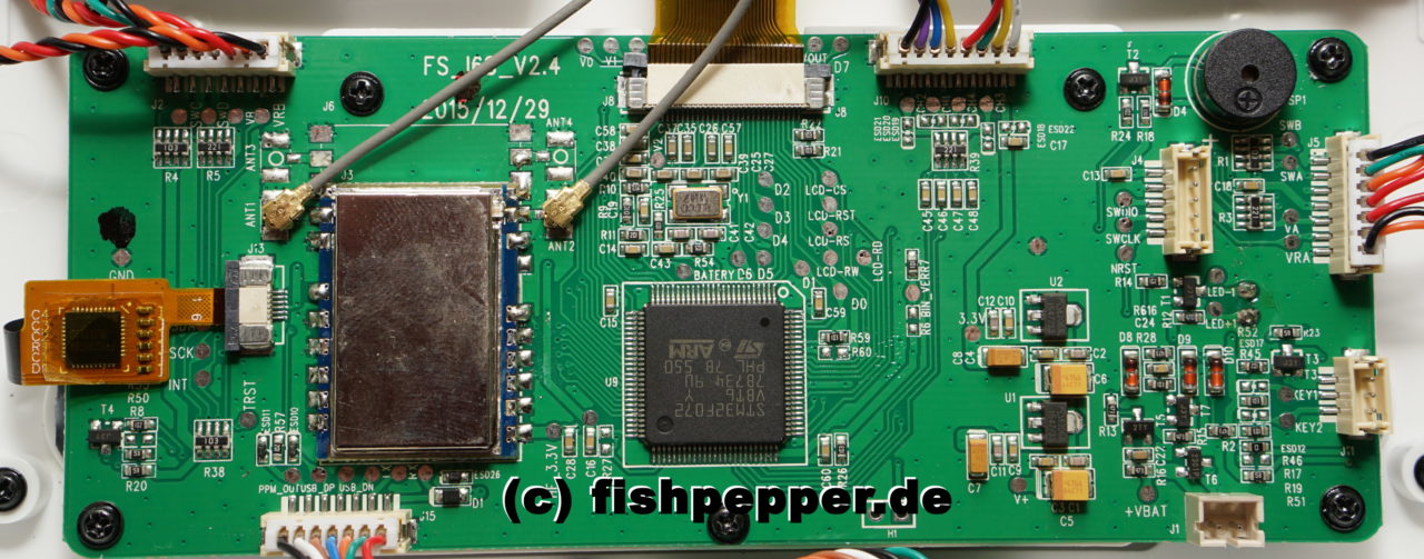
In order to write a custom firmware for the Flysky FS-i6s transmitter we will need to know which components are used and how they are connected. So let’s take a look at the PCB:
CPU
This board uses a STM32F072VB processor. It is a lower end processor of the STM32 line from ST. However it has some nice features as an unbrickable DFU USB bootloader, lots of peripherals and a nice DMA engine. And it’s programmable by the arm port of the opensource gcc compiler. The Datasheet can be found here.
Display
The display part number is written on its flat ribbon cable: HSG12864. A short web search reveals that this display uses a Sitronix ST7567 controller. Lucky for us, the datasheet is available online. The display is connected in 8-Bit mode with data lines D0..D7.
Touch
The touch controller is a Focaltech FT6236 controller (datasheet, application note). There is also a driver for this touch controller inside the linux source tree (code). The controller connects to the CPU via an I2C connection.
Pinout
Lets trace the pinout for the components used. As we are intersted in controlling these from the cpu, we will write a mapping from CPU pins to the individual peripherals. Lucky for us there are a lot of labeled (!) testpoints on the PCB. This makes it very easy to trace the connections.
SWD Port & BOOT pin
The programming port is accessible on the small connector J4 and on labeled test points (SWDIO, SWCLK, NRST, GND).
The BOOT1 pin is available on the resistors R59 and R60, short R60, connect the batteries and press the power on buttons to enter the DFU bootloader mode.
LEDs
Let’s start with something simple: the background LED. TODO: are there more leds?
LED_BACKLIGHT     = PF3 = PIN 22
BUTTON_LEFT_BLUE  = PD10
BUTTON_RIGHT_BLUE = PD11
Display
The display has some more lines, still easy to trace with the labeled testpoints:
LCD_D0  = PE0 = PIN 97
LCD_D1  = PE1 = PIN 98
LCD_D2  = PE2 = PIN  1
LCD_D3  = PE3 = PIN  2
LCD_D4  = PE4 = PIN  3
LCD_D5  = PE5 = PIN  4
LCD_D6  = PE6 = PIN  5
LCD_D7  = PE7 = PIN 38
LCD_RW  = PB5 = PIN 91
LCD_RST = PB4 = PIN 90
LDC_RS  = PB3 = PIN 89
LCD_RD  = PD7 = PIN 88
LCD_CS  = PD2 = PIN 83
RF-Module
The RF module is labeled FS-HS060 (2014.11.28 Ver1.2) and is probably an XL7105 transceiver module with an PA/LNA chip and RF switches for diversity and PA/LNA selection. We are not going to use this chip for our firmware.
RF_SDIO = PE15
RF_SCK  = PE13
RF_SCS  = PE12
RF_RF1  = PE11
RF_RF0  = PE10
RF_RX-W = PE8
RF_TX-W = PE9
RF_GIO2 = PB2
RF_GIO1 = PE14
Touch Controller
The touch controller IC FT6236 is connected to the I2C1 port of the STM32. In addition there are two control lines, one reset line and one INT output.
TOUCH_SCK = PB8  = PIN 95
TOUCH_SDA = PB9  = PIN 96
TOUCH_INT = PC12 = PIN 80
TOUCH_RST = PA15 = PIN 77
Buttons & Switches
Both power buttons have to be pressed together, single pushes can not be detected.
POWERBUTTON_BOTH  = PB14
BUTTON_BACK_RIGHT = PA10
BUTTON_BACK_LEFT  = PA9
Buzzer
BUZZER = PA8 = PIN67 (TIM1_CH1)
Analog
The sticks and all 2-way/3-way switches are read out with the adc. There is also the battery voltage on ADC10 (tbd: divider?).
STICK_LR_RIGHT = PA0 (ADC_CH0)
STICK_UD_RIGHT = PA1 (ADC_CH1)
STICK_UD_LEFT  = PA2 (ADC_CH2)
STICK_LR_LEFT  = PA3 (ADC_CH3)
2WAY_SWA_LEFT  = PA4 (ADC_CH4)
3WAY_SWB_LEFT  = PA5 (ADC_CH5)
JOG_VAA_LEFT   = PA6 (ADC_CH6)
JOG_VAB_RIGHT  = PA7 (ADC_CH7)
3WAY_SWC_RIGHT = PB0 (ADC_CH8)
2WAY_SWD_RIGHT = PB1 (ADC_CH9)
BATTERY_V      = PC0 (ADC_CH10)
The battery voltage is measured with a voltage divider (R10 = 5,1kΩ to GND, R9 = 10kΩ to signal) with an additional low pass filter (R11 = 200Ω and a capacitor C19).
Powermanagement
POWERDOWN_TRIGGER = PB15
I’d like to help with this project. Two things I’m looking to do is one replace the screen with something more colorful and improve the look of the user interface. Second and actually more important to to replace the RF module with the open source 4 in 1 module so I can use this transmitter with all the drones I have.