 A year ago i started to write my own opensource firmware for the VD5M receiver from FrSky. The stock firmware had no failsafe handling and I wanted to learn something about the 8051 CPU architecture. Since then i ported the code to the D4R-ii and added a lot of features. My code can output CPPM or SBUS and supports hub telemetry forwarding and much more. Please note that i am not affiliated with FrSky, this is just my personal hobby project and I do it for learning and for fun.
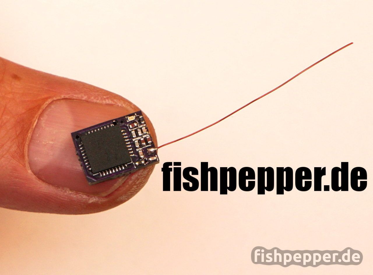
When i started to build my TinyWhoop there was no lightweight FrSky compatible RX on the market. This is why i started to build uSKY. My version of the world’s smallest FrSky compatible RX weights only 0.37g and measures 11.2mm x 8.51mm (the exact weight will be updated once i receive the 0.8mm PCBs). Nevertheless this RX has full analog and hub telemetry support and digital SBUS output. Of course it runs my opensource firmware and can be used with all your FrSky gear.

PCB
 The PCB was designed to be as small as possible and can be soldered by hand. However the tightly packed 0402 sized components require some experience with soldering SMD components. All you need for soldering is a small tip soldering iron, lots of flux and a steady hand. There is no need for a reflow oven, the ground pad of the cc2510 transceiver will be soldered from the bottom through a big via. This is not meant for mass production, it’s a hack to make it solder able by the experienced hobbyist.
Once i finished my testing of the current prototype i will post a link to my project on OSH-Park here. Make sure to order the boards in 0.8mm thickness to save some weight! The kicad design files will be released under an open hardware license soon. I just need further testing to make sure there is no design error on the hardware side.
The parts
Please refer to this google sheet for a list of the components I used for building the uSKY receiver. It includes some example part numbers for farnell and mouser. Please make sure to use high-Q high frequency parts where noted int this list.
The Design files
The design files are released under the CERN open hardware license v1.2. Before using the design files for commercial projects please make sure that you read and understand this license! You can use the files for your projects, just make sure to give proper credit (by e.g. linking to this page) and release all modifications you do to this design or work derivated from this under the same license.
You can find the design in the kicad file format on my github repository here. If you want to skip the hassle of rendering the gerber board files on your own you can simply skip this step and checkout and order the part from OSHPark:
- with filled silkscreen zone (looks nice but sometimes the silkscreen is shifted making this hard to solder)
- withouth this zone
OSHPark offers a really great quality for a ridiculous low price (it is 0,70$ for three copies!). Make sure to order the 0.8mm version in order to save some weight.
Component placement
Please refer to the following to pictures for component placing for soldering:


The ground pad of the CC2510 has to be soldered through the big via. Apply lots of flux and use the soldering iron to solder it from the other side. This is a hack to make this board solderable by the average hobbyist and this is NOT recommended for any serious designs 😉
Firmware
The uSKY RX runs my opensource OpenSky firmware. The master branch has support for building for this target (set TARGET=USKY).
Building & Flashing
I will add a tutorial the next days. For now stick to the guide how to flash the vd5m. Use TARGET=USKY for building the source and connect the CLK, DATA, RESET, GND, and VCC lines in the same way as on the vd5m.
Disclaimer
Please refer to my disclaimer that applies to all projects presented on this blog. Make sure that you do not violate any transmission laws in your country.
Hi, thanks for sharing the projects they are great. Any ideas on how to make this compatible with flysky?
This is not that easy, Flysky uses a different receiver chipset 😉
It is awesome what you are doing! First thought about when you talked about soldering SMD, reminded me of something someone once showed me. Basically tack down one pin to hold chip in place. Then solder all the way across one side, don’t worry about bridging. Then you go back over that side with solder wick. This should leave no bridges and a very clean solder look. I guess not everyone may not have solder wick around, but give this a try if you haven’t done it before. I was never officially taught how to solder per say but found this much easier than going pin by pin. Just thought I would offer my brief experience with soldering SMD.
That’s exactly how I solder manually when I am not using hot air. Adding good gel like flux also helps a lot. However, I do not use this technique much after I bought my cheap hot air station (see https://fishpepper.de/2017/09/06/the-best-hot-air-gun-for-your-quadcopter-hobby-35-to-the-rescue/). It is just so convenient to add some solder paste and let the hot air do all the magic 🙂
Hi Simon. I just have finished my Usky board. Everything fine, red led light up when power on, short Data pad to ground, the led in the bottom side of PCB solid but i can’t bind. I press bind on my taranis but nothing happen, i try to replace new 4 CC2510 but i can’t bind but if i replace it on XM+ and port the FW to XM+ it’s bind perfectly.
Do you have any suggest for me ?
You will have to use the international D8 mode! The firmware does not support the newer EU firmware.
first of all i reaally am interested in tiny fc since it has an internal build in receiver… few questions that comes to mind… 1. what port / uart should i turn on in betaflight in order to activate the build in receiver (serial rx)? 2. just curious… if for some reason the build in receiver is broken and cant be fixed… can i put an external receiver and solder it on uart 3 rx?
The settings are stored in the tinyfish bf firmware. Just load the defaults and you are set. Of course you can add an external rx to the uart3 pads next to the usb port.
It might be helpful to document that it is MUCH easier to bind before installing. I doubt that anyone is going to use the provided connector on the small builds this little rcvr is being used on. I clipped it and soldered directly to my flight controller. Now I discover that bind requires soldering to the ground pad – where the ground wire is already soldered. With such small pads and already being mounted in my build, it is a pain to solder jumpers, bind and then resolver the existing ground. Wish someone had mentioned that before so I am now.
You can use any ground pad, even the big center hole.. I bound mine by sticking pointy tweezers into the center hole and touching the pad while powering on.
Hi Simon.
First of all, congratulations for the nice projects you have, and many thanks for sharing your projects. Learn a lot with them, and still learning.
I am waiting for boards and components to build a uSky rx.
Don’t quite get your sugesttion to solder the CC2510.
“through the big via”, “from the other side” ?
Could you please explain in more detail ? Or is there any youtube video with this technic ?
Thank you very much.
José Moutinho
Start by soldering it from the top side. Solder all the pins from the side. Then turn the board over and add some flux to the center hole. Take a 2-3mm big soldering tip and add let some solder flow into the hole. In case your soldering iron is not powerful enough increase the temperature a bit.
Thank you for the clear explanation.
After the components arrive, I will let you know if I managed to build the uSky. I guess I will.
Best regards.
Hi, what is the correct antenna lenght? Because I have the tinyFISH FC from Boldclash, and the antenna is approx 36mm, which seemed a little long to me. Aldo the range is not impressive. Should I shorten it?
You can try to shorten it to lambda/4 (3.12cm)
Hi Simon,
Do you think it would be possible to implement s.port telemetry for uSky/tinyF1sh receivers ?
I’m sure many people would be interested in using s.port telemetry to change Pids with a controller running OpenTX 2.2
Might be done in the future. I just do not have the time for that :-\
New chinese manufacturers copy of uSky flashed with the 0.2.1 OpenSky firmware https://www.banggood.com/8CH-SUBS-Mini-Compatible-Receiver-for-Frsky-X9D-Plus-p-1156900.html?p=V9061370462720140842
How to off telemetry this rx ? I want build again hardware with range better
Hello,
Do you think that it is feasible to connect from TARANIS X9D to have the RC control which would be output as CPPM and not SBUS and connect at the same time from another CC2510 module to have an half duplex link to transmit serial data.
I think there is at least some code to develop but i would like to know if it’s feasible from an hardware point of view.
Very nice project
I’m sorry to bring the bad news but it seems that the chinese manufacturers copied and reproduced this design without consent.
https://www.banggood.com/IRangeX-RX803-Super-Micro-Receiver-Compatible-Frsky-D8-X9D-Plus-SBUS-Output-p-1147916.html?p=V9061370462720140842
They did quite a horrible job with the cables from the connector and the antenna that looks not to be the correct length.
Wow, interesting to see that they really mass manufactured this hack :-X
To be honest, did you really expect them to do a PCB revision?
I did not expect them to be able to manufacture this ugly hack *g*
Hi Simon,
Is it at all possible to use other variants of the CC2510 chip? Such as the CC2510F16RSPR or CC2510F32RSPR?
Yes this should work as well.
Hi, First of all thanks you for the opportunity to test your design, great work.
Have mounted 2st usky and programmed them. Seems to work, at least partly, but I’m now working on the bind procedure. From what I understand, I have to short the data to ground to enter binding mode.Is there other ways to do this and can I expect some response on LEDs? For now I have solid red (backside).
Device information:
Debug status:
[X] CHIP_ERASE_DONE
[ ] PCON_IDLE
[X] CPU_HALTED
[X] PM_ACTIVE
[ ] HALT_STATUS
[X] DEBUG_LOCKED
[X] OSCILLATOR_STABLE
[ ] STACK_OVERFLOW
Debug config:
[ ] SOFT_POWER_MODE
[ ] TIMERS_OFF
[ ] DMA_PAUSE
[ ] TIMER_SUSPEND
pi@raspberrypi:/boot/Python/WiringPi-Python $ sudo python ../cc_reset.py
Hello from ccraspberry
Using CCDebugger on port ccraspberry
182
detected a cc2510f16
Chip information:
Chip ID : 0x8104
Flash size : 16 Kb
SRAM size : 2 Kb
USB : No
Do you get blinking LEDs on powerup with no shorted pads?
Have two cards. One one sek. on green(toplayer), a shorter on red then short faster on green.
The other the same but solid red after.
Will try debugport to see if I can get some more info.
I’ve got it to bind now.
Hi,
I just opened kicad project, kicad_pcb file cannot be opened.
Which version of kicad are you using?
You have to download the latest (nightly build, not the stable release).
I have finished working on PCB soldering. When I connect the lines to cc-debugger(CLK-3, DATA-4, RESET-7, GND-1, 3.3-9) and ready to flash. I found that no matter how I press the REST button, the LED on the debugger are always red.I check the picture, I found 5k6 is not in the BOM. Is this the source of the problem?
Hi Simon,
Love the boards, just built up 3 and about to program them. I would recommend that you remove the all over silkscreen from the top of the board…The boards I got from OSH there is a registration issue which makes the text look really cool and 3D, but also makes the pads much smaller and harder to solder without a lot of scraping.
Good idea! Here you go: OSH Park – uSKY without silkscreen zone
Hi,
I am beginer, how to create the hex in windows ?
Or can you post the hex file ?
Best regards
Vincent
When I open usky kicad project,kicad warn not found atmel.dcm,cannot find special.lib.what’s wrong?how can I solve it?
Did you install the kicad libs? You can ignore those warnings, I do not use parts from special.lib and atmel.lib 😉
Hi Simon! Tem same problem about the placement diagram, where is the red LED and red LED place? Can you fix the picture?
The one on the top layer (red layer) is D1 (green) with R6=330Ohm. The one on the green bottom layer is D2 (red) with R4=220Ohm.
Hi Simon,
I’ve got my PCB from OSHpark, When I compare the BOM and circuit board production figure, I found there is no placing for R4 & R6 on the figure. I wanna get ur help to figure out how to make a right application about the extra R4&R6.
Sorry for that, the original placement diagram still lists the placeholder values (the 1k resistors in series with the LEDs). Use R4 as the in series resistor for the green LED and R6 for the RED one.
how/where did you order the oscilator? mouser wants to sell 3000pcs only. 🙂
I got mine from this aliexpress seller.
Hi Simon,
I just finished building this RX and find a problem when binding with my Taranis. I got some logs from the DEBUG port, it always printing like “———————————————————-BBBBB———————————————————————————————————————————————————————————————————————————————————–frsky: RXOVF”. What’s that for and how can i bind with my TX. Looking for your reply. Thanks..
Looks like it at least detects some packets. How far away was the TX? Try to move the tx at least 1m away from the rx during bind and try again.
Thanks Simon! Last question 🙂 What would be the best way to make voltage monitoring using analog telemetry input? I want to monitor 1S lipo voltage, as it seems that my FC does not supply such function. Do I need a voltage divider here?
Yes, use the pad labeled ADC0. Make sure to use a voltage divider to make sure the input does not exceed 3.3V.
If you do not use hub telemetry you can change the config.h (change #define ADC1 7) and use the pads of the voltage divider resistors and ADC1 input.
As i use telemetry i do no longer use those adc inputs.
I cannot get hub telemetry to work – which pad on the uSKY is supposed to receive the telemetry data from FC’s UART TX? (firmware compiled from source with no changes) I cannot find any mention in the code, there is something about shared SBUS pin, I tried connecting TX2 to ADC0, ADC1, and SBUS pad, none of them worked… Should the telemetry be inverted or not? Is SmartPort auto baud ok, or do I need to set it? SPort_halfduplex ON or OFF? (Although I’m assuming ON as setting it OFF breaks the communication with FC)
I would really appreciate a little help here. Once I get it all working I’ll write some documentation on the uSKY and make a pull request on github for you to merge if you would like 🙂
I answered you on rcgroups. Sorry for the delay.
Hi Simon! I’m building a usky RX for my TinyWhoop as well, currently waiting for shipping from OSHPark 🙂 I will send you a few pictures of my soldered rx as well. Thank you for this great design!
One question though – how do you enter bind mode?
Just short the ISP data pin to ground when powering up the rx 🙂
Hello, I download the source code, in the UBUNTU environment, how to use the SDCC compiler HEX file
Install sdcc and simply run make in the source folder 🙂
Hi Simon,
Any chance to compile BOM for uSKY with link to farnell/whatever like you have done for pepperF1SH ? 🙂
I just updated the BOM to a google docs sheet. You can find it here.
Hi Simon,
i found this [1] crystal on farnell (moq 5) and digikey (moq 1). That should work for the both uSKY and the tinyfish FC, right?
http://de.farnell.com/txc/8y-26-000maaj-t/xtal-26-000mhz-18pf-smd-2-0x1/dp/1842182RL
https://www.digikey.de/product-detail/de/8Y-26.000MAAJ-T/887-1152-1-ND/2119055?curr=eur&WT.z_cid=ref_octopart_dkc_buynow&site=us
They should do, they are rated at 30ppm (cc2510 requires < 40ppm).