In this post I am going to share all the parts you need to build your own super lightweight tinyFISH flight controller with an integrated, FrSky compatible rx. All the following information applies to the current version 0.2b of tinyFISH (tagged as revision 0.2b).
Changes compared to the previous revision 0.2:
- fixed the numbering of the esc pads
- changed vreg to 3.1V
Circuit board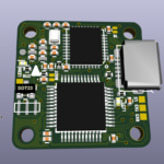

The PCB was designed to accommodate all the features I wanted in the smallest form factor possible. The outer dimensions are 20x20mm with a hole-to-hole distance of 16mm (M2). When manufactured in 0.8mm FR4 the completely assembled board weights silly 1.7 grams. This was only possibly by using small components, manual placement, and several tries on routing. The final result, tightly packed with 0402 sized components, require some good experience with soldering SMD components.
BOM
I updated the BOM a bit, you can now find a table with part references and ordering numbers for farnell and mouser on this google doc sheet. Please make sure to use high-Q high frequency parts for the hf section around the CC2510 chip as noted in the list. I ordered the majority of the parts from Farnell but you can probably get most of the parts at any electronic component vendor. Make sure to buy the MPU6000 from a reputable seller, I got some bad quality (fake?) chips from aliexpress…
Design files
The design files are released under the CERN open hardware license v1.2. Before using the design files for commercial projects please make sure that you read and understand this license! You can use the files for your projects, just make sure to give proper credit (by e.g. linking to the tinyFISH FC page). Additionally release all modifications you do and all work you derivate from this under the same license.
You can find the design in the kicad file format on my github repository. You will need a recent version from kicad. I compiled my own binaries from kicad commit efdfaeb.
If you want to skip the hassle of rendering the gerber board files on your own you can simply skip this step and checkout and order the part from OSHPark.com using this Link (rev 0.2b). They offer a really great quality for a ridiculous low price (it is 3$ for three copies!). Make sure to order the 0.8mm and 2 Oz copper version in order to save some weight.
Placement & Connections
You can use the following diagrams for the component placement. See my github repository for the full resolution files in SVG format.


In addition to the part placement, those diagrams do also show you how to connect the various signals to this fc. The pads labeled CC_* are the ISP connection for the CC2510 and are used to flash the initial CC2510 bootloader.
Do it!
Now it is time to build your own! This page has all the information you need to build your own tinyFISH flight controller. Sure, this required very fine pitch soldering, but if you have some experience with SMD soldering give it a try! If this sounds to complicated to you, do not worry, I am quite sure someone will pick this design up and sell it sooner or later.
If you have built any my stuff I would be happy to see and hear how it turned out for you — send me an email!
Hello,
I have bought a tinyFISH. it work very well, but I have a problem, I have broke the “wire” of the ant.
can you explain me how to replace it? Is it coax wire? or only a simple wire? is the length important?
thanks a lot
It’s just a simple wire. Cut it to lambda/4 (=3.125 cm).
Simon, thanks for all your work on this board.
I’d like to connect a specific pressure sensor to the board (MS5803-14BA). It has I2C and SPI comm’s – would you know if there’s a simple way to wire directly to the pepperfish? (via UART3 pads maybe?) Is there a betaflight setup that would log from that port?
Any suggestions would be welcome.
Thanks for designing the tiny fish and offering this amazing tiny fc to the public.
I got my tiny fish (assembled from banggood I know that they are just copy cats and I felt short sorry after discovering your work (during debugging of issues with full batteries)) and bound it to my Taranis… which worked fine for some months… Now I brought a Frsky X-lite and tried to bind it again (international D8 version), however this didn’t worked. I thought that there is some issue with the firmware and therefore I flashed the most recent release (0.2.1) from github using a cc debugger.
Now it doesn’t bind with the Taranis either… (when I hold down the button during powering up the green led is solid and the red led is off , I then enter binding mode of the transmitter but nothing changes… I also tried to increase the distance between fc and transmitter to approx 2 m…
Has somebody a clue what I’m doing wrong or what I have to check.
Don’t worry, no need to feel sorry.
I am not sure which pcb revision they used, It might be that they used a different pinout than I used for the last revision. If you want you can send me high resolution pictures of the top and bottom of your PCB. I can have a look then.
Strange that it did not bind before flashing. Did it still bind to your Taranis before the flashing?
I have compared the pcb to the KiCad files provided on Github… I think they have used v0.2… I have send you highres photos thanks for having a look on it.
I could not check if the taranis binded before flashing as the taranis was bound and therefore it doesn’t made a difference… Could it be that the cystal of the CC2210 is out of spec and therefore the bind procedure is not possible. However this doesn’t explain why the control by the taranis worked before flashing (I’m not familar with the Frsky D8 protocol with regard to frequency hopping) … Also the two way link was operational as the transmitter reported low RX signal when the Tinyfish was powered down.
Hi Simon, I have 2 successful Tinyfish and tinypepper builds under my belt. I love the whole packge and look forward to building the next esc you decide to share.
Here’s a video of my first built set in a 1s 85mm quad.
https://youtu.be/czAvQT4T1cY
Thank you for all these great projects and for sharing in many others.
Did you build the FC and ESC on your own? Congratulations! Thanks for sharing this!
I just completed my first tinyFISH FC build and this is by far the most challenging FC build that I have undertaken so far. Thanks to Simon again for the chance to do this.
PS – I decided not to fit the chip for Blackbox at this stage but maybe in the future
Some images of the completed board
https://imgur.com/a/CJntv
https://imgur.com/a/70vEm
Congratulations for your successfull build! That looks quite good! Where did you get the PCBs made? Thanks for sharing teh pictures.
I got the PCB’s from your OSH Park link Simon. Looking forward to getting it into a build once I decide on one 🙂
Just one other thing that may interest anyone wanting to use a Deviated Devo 7E TX fitted with a CC2500 module. I had some problems binding but after some help on the Deviation Forum I got it all sorted out here. https://www.deviationtx.com/forum/6-general-discussions/7436-tinyfish-fc-bind-to-7e-with-cc2500
I was wondering because they look black on your pictures. Is it just the light or did OSHPark start selling non purple pcbs?
They are still purple but under the pretty crappy USN microscope they do look black 🙂
Just to let you know the notification system for replies here does not work either. I have both boxes ticked and never get notifications.
Ah ok. It looked so dark that I never thought about this could be purple *g*
Thanks for letting me know about the notifications. I applied some fixes and it should hopefully work now 🙂
What is the purpose of v out +? I have purchased two different stacks a luminier and a boldclash. The luminier had the battery input pigtail connect directly to the esc and wires from the esc to the in – and in +.
The boldclash has the battery input pigtail connected to the fc in – and in +. Then out – and out + is going to the rec.
Which way is the correct way?
Lastly using the new 1/2s esc what is the correct way of wiring that one to the flight controller?
You should connect the battery to the in pads. Then add some wire and connect all peripheral parts like the ESC or the cam to the out pads. This way you will have current meter readings in telemetry 🙂
Think I have problem with radiopart on my TinyFish build. Looking for suggestion on how to find out exactly what is wrong. Using the 0.1 rev of pcb and have tried all different fw rev. for now I’m testing the latest. When powering on, with or without bind jumper set I’ve got solid green light. Have usky since before so have confirmed bind procedure and also have compared 26Mhz between the two of them, not super accurate since I using an old 20Mhz scope. Have tried to monitor debug data. From what I’ve can see it’s no signal on that pin. Also tried the boot mode (data pin ) and got flashing red and green – guess thats a sign that fw is running ok since detecting boot pin shorted.
Do a visual inspection if all pins of the stm32 and the CC2510 chip are soldered properly (no visible gaps, no solder blob shorts, etc).
Or maybe the bootloader fw is ok and the main fw is bricked? You could try to update the rx firmware by following these steps.
For the U5 flash memory in the bom, the package is showing VFDFPN8
the farnell id is also link to M25P16-VMP6G having the VFDFPN package
However the value is M25P16-VME which i believe the package is VDFPN
Im confused, which one is the correct one?
and this component seems No Longer Manufactured as shown in farnell, any alternative recommendations?
Thanks!
Racerstar and others managed to mount the normal soic8 version onto the pads. Seems like the pads are good for both types 🙂
I selected the other type mainly because it was less high.
HI,
I am building 2 board right now and have to admit, I hate 0402…
how long is the antenna? Is there a possibility to optimize SWR using RFStudio?
Great project by the way, thanks for ur effort.
BR
Joerg
hej there o/
since i’m a 100% hobbyist i’ve no clue how to read that google-list. probably someone could tell me if the “B” section ist the quantity of the parts needed to build up the fc and what “E” section stands for?
another big thing i don’t get is where to find the circuit diagram to know where to solder the parts.
the idea to build a fc with my own two hands (still waiting for 2 brushed replacements from china) to repair friends micros is fantastic. i’ve very steady hands, a lot of patience and time.
made a mouser account to get all parts in line and am planing to get the boards from your linked (community driven) vendor.
i’m in the hobby since 5 month and repaired a lot of stuff. had to solder (repair) a lot on these tiny boards and never had a problem so i thought to give it a try.
thanks a lot for your invention and the move to made it free knowledge <3
o/
Just completed 3 flight controllers and 3 speed controllers. Thanks for releasing such a wonderful project. This was my first time doing any SMD work so while a challenge it was very rewarding. I will be installing these into 2 self made frames in the next few days and keeping one set as a spare. I cant wait to get these flying and waiting for your next add on project…
Thanks again for your efforts.
Jayson
Hi Simon, I’m about to have a go at building and can’t find any source for the crystal. I’ve tried Farnell, Digikey and Mouser where I get most of what I need usually but they are all out of stock. Is there an alternative or do you know anyone with stock?
Cheers Steve.
I got mine on aliexpress, see the links on usky page
I managed to find some in stock at Arrow.com thanks. A few items are challenging to track down but I have all I need on it’s way, next challenge is the build.
Excellent design!
But could you remove the M25P16-VME?The PIKO BLX flight controller had remove this component,This can make the controller more chipper and more smaller.
sorry,i means more cheapper and more smaller
Hi, I’m having some trouble with the RX – I’ve flashed the CC2500 firmware and it seems to be operating – I get a solid green LED, and if I power up with bind pressed it’s rapid flashing instead. However, can’t seem to bind and I never get any activity on the receiver panel in betaflight. I’ve tried to hook up to the debug port, but I don’t see any data there. Any suggestions?
I have successfully completed the flight controller! I had to rework the receiver portion a little, and after some trouble managed to flash it using a raspberry pi.
Dataflash, current sensing and everything appears to be working!
Sam
Congratulations! Thanks for the report!
Hi, I very much like Your desing of FC & ESC and I appreciate very much the efforth You have put in.
There is one tiny thing which I think would be beneficial in further revision – the FC & ESC board interconnect. Now it means that a bunch of cables has to be soldered on and squezzed between the two boards. Nice board to board pins(or pinhead) or aligned side connections (similar to motor pads) would simplify this and it would save some weight too.
Was just about to order stuff from Farnell/Mouser. Unfortunately, neither has X1 (the 26MHz crystal) in stock.
Are there any replacement parts you could recommend? E.g. any of this list: http://ch.farnell.com/webapp/wcs/stores/servlet/Search?rd=quarz&catalogId=15001&langId=41&storeId=10178&categoryId=700000005191&sort=P_PRICE&st=quarz&selectedCategoryId=%5BLjava.lang.String%3B%4041ad41ad&pageSize=100&beginIndex=1&showResults=true&pf=312004323,312004448,312004450,312004451,312004452,312005704
Thanks a lot and have a great day!
Sorry to hear about the clones, parts and boards are on order and will be encouraging my club memebers to do the same and support open source!
We appreciate and probably dont even understand the time and effort you have put in to this.
Hi, I am really interested in building this, because I also own a micro wich has too much weight for indoors and I don’t want thoose brushed copters. But I have a Spektrum transmitter. Is it possible to build somethin in this size with a Spektrum reciever?
Thanks for reading! Have a nice day!
A friend of mine flies spektrum as well. We did not pupolate the tx part of the tinyFISH fc and he added an external small dsmx satellite.
Would it be possible for you or your friend to show us how the Spektrum sat was added to the tinyFISH FC and the firmware changed please Simon. Sort of defeats the purpose of the built in Usky RX but I would love to know how to do it please.
He simply wired it up to the spare RX port on the lower right corner (TX3/RX3). No firmware changes, just betaflight config to set up the spektrum sat. He powers the sat from the 3.3V stepup voltage on the vtx/cam combo (no dropouts).
Thanks for the reply Simon. Just completing a Digikey cart and looking forward to the build 🙂
Is there a way I could make spektrum work on a premade board. I would really like to build one and preferably be able to buy the complete stack off of get fpv. Can I just like cut a couple traces or something to make the integrated rx not work and then add an external rx.
No cutting is required, just add a spektrum RX to the pads labeled RX3 and TX3 (uart3) and reconfigure betaflight to use a spektrum rx on uart3 🙂
A friend of mine is actually flying that kind of setup. If you go 1S make sure to get a rx that works on 1S, some have spurious resets on low battery…
I cannot configure iBus on UART 3. It always defaults to “Disabled” after save and reboot.
Is it a valid combination with Tinyfish FC? I am using FS-A8S RX to RX3 connector and 2S power.
Did you disable serialRX on uart1? I am not sure if bf allows you to configure two serials as serialrx.
Maybe I missed it somewhere, but why the change to the 3.1V regulator? Was 3.0V causing issues somewhere? I’m making an FC very similar to this for a drop-in replacement for the Inductrix.
Thanks for all the great work, especially the uSky which is just awesome that someone did that. 🙂
The problem with the 3.0V reg was that my tinyPEPPER esc runs on lipo voltage. An efm8 with vcc=4.2 will not always detect 3.0V as logic high. 3.1V seems to do the trick for all efm8 boards I populated so far.
The 3.1V reg is just a drop-in replacement for the older revision board as well, right? Just received rev 0.2 from oshpark, wondering if just this replacement could work
It is a drop in replacement. No board changes were made for that 😉
und da ist auch schon der erste Lizenzverletzer. Ging ja schnell.
http://www.banggood.com/Racerstar-F3D8-16X16mm-Micro-F3-Flight-Control-Board-Built-in-8CH-SUBS-Receiver-for-Frsky-X9D-Plus-p-1136734.html?p=V9061370462720140842
It’s a little sad, that the chinese clones are faster than i can procure all the parts 🙂
I’m going to build my own anyways and if it’s only for the challenge and newly acquired skills.
Go ahead and build it on your own. You will learn a lot 😉
Boards arrived today! Just gotta order some passives and I will be building a full FC and ESC Stack! I will let you know how it turns out!