This is the sixth post of my series documenting the development of a custom firmware for the FS-i6s transmitter. In my previous post we dealt with the LC-Display, this time we will set up the STM32F0 ADC in DMA mode.
Sticks’n’Switches
 On the FlySky FS-i6s transmitter, all sticks and switches are connected to the analog input pins of the analog digital converter. This way it is e.g. possible to read out the 3-way switches with one pin. Different switch positions correspond to different voltage levels archived by a resistor network connected to the switch. In addition, there is one voltage divider that can be used to measure the battery voltage. In total this sums up to 11 ADC Channels.
DMA?!
The nice thing on the STM32 series of chips is the configurable and feature rich DMA engine. Once set up properly, the DMA engine can be utilized to copy the ADC results to a given memory location in the background without wasting any CPU cycles. Thus we will set up the DMA engine to read out all eleven ADC Channels.
The ADC code can be found in my github repository in the file adc.c. Before we can use the ADC pins we have to configure them to be in the GPIO_Mode_AN mode (adc_init_gpio()) . The sticks, sliders and switches are connected to ADC channels 0 to 10 (see the pinout post). Please note that the first 8 channels connect to PORTA, the next two are on PORTB, and the last one is connected to PORTC.
Next, we will have to set up the ADC channels and the sampling frequency, this is done in adc_init_mode(). We configure all eleven channels, enable the ADC1 and activate the DMA for ADC1.
The DMA engine is finally setup in adc_init_dma(): We configure basic peripheral to memory operation, set the source to the data register of ADC1, the target to our memory buffer, and the data count to 11. Afterwards the DMA is enabled and the first conversion is triggered by calling adc_dma_arm().
Every time we want to sample all eleven channels, all we have to do is to call adc_dma_arm() and wait for DMA_GetITStatus(ADC_DMA_TC_FLAG) to become true – the conversion was finished. The data is now in the previously defined array in the main memory.
Try it out
You can compile an test the code on your own, check out the tag part6_adc_dma and build the code (this requires the arm gcc toolchain to be installed):
git clone https://github.com/fishpepper/OpenGround.git
git checkout part6_adc_dma
make
After the code was compiled we can now flash the code to our transmitter. We will use the ST-Link interface to flash the chip. The makefile has a nice macro for that, you can flash the target by executing:
make flash
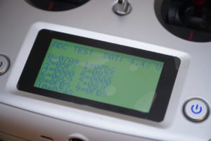
The screen should now be initialized and you should see all eleven ADC channels. If you move the sticks you should see the values change.
