[hier geht’s zur deutschen Version des Artikels]
This is a blog post from Holger, another copter fanatic from my hometown Bielefeld 🙂 Thank you very much for giving the permission to share this build log with my readers. The original article was written in German, if you find any spelling/grammar bugs in this translation please blame me (fishpepper) for this 😉 And now enjoy the article:
… and it’s quite easy… The sub 250g Copter
 When I browsed the Internet for new copter stuff those new 20x20mm flight controllers catched my eye. Having designed and built several sub250 copters before, using “oldschool” 30.5×30.5 flight controllers, it was time to try something new.
Fireing up the 3D software and… Time for a coffee break. More coffee. Some more coffee 🙂 And then… The breakthrough, I am sitting in front of the PC again! Some hours later I finished the second version of the sketches for 3″, 4″, and 5″. Those plates differ in arm length and width, but the stack assembly holding the electronics are shared among all versions.
The design process was done having weight optimization in mind, not building the most crash resistant copter. This becomes evident for the 5″ version, those arms, thinned to the absolute minimum to stay below 30g for the frame, are most likely to delicate to handle some major impacts.


(click the images to enlarge)
Depending on the requirements of your electronics stack, the main compartment can be built in 25mm or 30mm. Again, there is only one assembly version for 3″, 4″, and 5″. This build log will show the 4″ copter with a 25mm main compartment.
The complete design is done and double checked for a good fit in 3D before being exported in a format that my regular CNC workshop (www.4spower.de) uses to cut frames. You can find the files in the DXF format in my dropbox folder.
Please refer to this dimension overview in case you want to use different electronic parts:
The first rendering in 3D looks quite promising:
All in all the 3D tool chain estimates an overall weight between 28g and 30g for the full frame — not that bad!
It’s done!
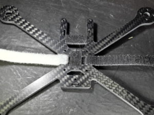
Finally the CNC cutting can be commissioned. I sent the DXF files by mail and the postman delivered the cut frame the very next day! The 3″ 25mm version was cut and delivered in record time. As always, my CNC cutter Kai delivered perfect work, all parts fit nicely together, as I am used to. Heave a sigh of relief. In addition, there are lots of spare parts — that’s what I call good service!
The estimated weight was beaten, the picture shows the assembled frame that includes spacers and screws: 28.9g! The 4″ version got a bit lighter 🙂 The baseplate is made in 3mm, the stack is 1.5mm and the FC plate is made in 1mm CFK.


(click the images to enlarge)
And now the final question… how expensive was that? Well, a bit more expensive as made in china, but worth the money 🙂
Installed hardware
Time top go shopping!
| FC | HGLRC XJB F425 or F428 | fpvcopter.de or Banggood F425 / F428 |
| TX | Tramp HV video transmitter | multirotorparts.com or Banggood |
| Antenna | linear antenna | multirotorparts.com or Banggood |
| Receiver | Frsky R-XSR | fpv1.de or Banggood |
| Motor | Brotherhobby T1 1407 | |
| 4100KV for 3″ Propeller | fpvcopter.de | |
| 3600KV for 4″ Propeller | fpvcopter.de or Banggood | |
| Camera | Runcam Swift Micro 2.1mm | rcheli-store.de or Banggood |
| Battery | 800-850mAh 4s Lipo | e.g. from this one from SLS |
Add some smaller parts:
- active buzzer
- XT 30 connector
- 3x25mm M2 aluminum spacer
- Screws: 6xM2 8mm, 2xM2 6mm, 16xM2 5mm
- Loctite medium
- M2 nylon spacer, -screws und -nuts
- 15 AWG silicon wire
- 30 AWG silicon wire
- Plastidip or similar (weather proofing)
- double sided sticky tape
And finally the frame:
- 3“ V2 25mm frame from this dropbox folder
- 4“ V2 25mm frame from this dropbox folder
If you want to get this frame cut feel free to contact Kai from 4spower.de (kai@4spower.de). He delivers very professional and high quality. He provides fast processing and shipping times plus all machining is made in Germany. International orders are also welcome. Just ask for a quote 😉
Kickoff! Heat your soldering station!
Before starting with assembly I will pre tin all necessary solder pads. Skip the unused ones, every gram counts and as you know lead is quite heavy 🙂
The needed pads:
- VTX
- Camera
- Buzzer (BB- and 5V)
- Receiver
- (I am skipping the LEDs for now)
Tin TX3 and TX6 on the other side of the FC. Both pads will be used to transfer telemetry and settings of the video transmitter via the OSD.
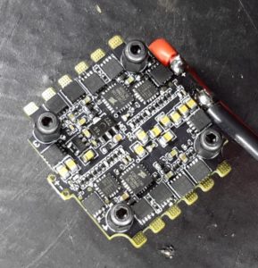
Next, tin the pads on the upper side and the battery tabs on the lower side of the 4in1 ESC.

(click the images to enlarge)
The tiny FrSky R-XSR can be mounted below the 4in1 ESC. Use the 5 pole plug with silicon wires that comes with the receiver.

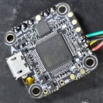

(click the images to enlarge)
- removal of the white cable (SBUS_IN) as we will not use redundancy
yellow wire to TX3 (SmartPort)- green wire an SBUS
- black wire to –
- red wire to +
Ooooops… FAIL!
The SPort signal of the R-XSR can not be connected to TX3 but has to run over a soft serial port if one does not want to solder to the micro pad on the R-XSR. I did not notice this at first as the battery voltage and RSSI were shown correctly in the OSD, but VFAS (battery voltage) was not forwarded to the taranis when connected to RX3.
Betaflight allows to remap single I/Os of the flightcontroller. This is done by using the resource command in the CLI mode. Entering resource in the configurator CLI the current mapping is printed.
The SmartPort pin of the R-XSR should get its data via the PPM pad of this FC. Checking the manual of the FC shows that this signal pad is routed to the Pin B14.
What else connects to B14? The default settings show:
- resource PPM 1 B14
- resource PWM 1 B14
- resource ESCSERIAL 1 B14
Ok, let’s free up B14 by issueing this commands:
resource PPM 1 NONE
resource PWM 1 NONE
resource ESCSERIAL 1 NONE
save
done. Now assign B14 to the softserial:
resource SERIAL_TX 11 B14
save
Now it’s time to connect the SmartPort cable to the R-XSR:
The missing step is to activate and assign the soft serial port in the betaflight GUI. Do not forget to save — been there, done that 😉 When done, the ports tab will show your softserial1 port. Activate SmartPort on that serial port and save again.
Just a short check if all is set to the proper values:
get tlm
The right response should include:
tlm_switch = OFF
tlm_inverted = OFF
tlm_halfduplex = ON
pid_in_tlm = OFF
Fine. Now shorten and solder the six pin cable from the trampHV to the FC. The wire has to be long enough that the VTX can be placed on top of the stack. Remember, every gram counts 😉


(click the images to enlarge)
- red goes to BAT (battery voltage)
- yellow to VTX (video signal)
- black to – (GND)
- white to TX6 (settings)
- orange delivers 5V to the camera and stays open for now
Add the beeper, make sure to double check for the right polarity:
Now prepare the frame:
- take some sticky Velcro and cut it to the proper width and length
- mount the fluffy side to one side and the rough side to the other
- make sure to have equal length on top and bottom before joining them
- join both sides, see picture
- add some Velcro to the frame
- add some Velcro to the top and bottom of the lipo battery
The Runcam micro comes with a three pole plug. Again, cut this wire to the correct size. Make sure that the camera can be tilted freely in its mount without over stretching the wire.


(click the images to enlarge)
- red to the free orange wire of the trampHV
- orange to +5V
- yellow to CAM (Video OUT)
- black to – (GND)
- beeper goes to 5V and BB-
As I took the motors from a previous build where I shortened the motor wires significantly, I had to add new wires.
Temporarily mount the motors and fixate the motor wires with clear sticky tape. Shorten the wires and solder them to the motor tabs of the ESC. Make sure to connect each three motor wires to one ESC output, the ordering of the single phases and thus the rotation orientation does not matter, this will be configured by software.
Time to get sticky!
The TrampHV, R-XSR, FC, ESC, and Camera have to be protected against humidity. (Addition of myself: Every time there is a time slot for flying the chances are quite high that it will start raining here in germany at exactly that specific timeslot…)


(click the images to enlarge)
Route the battery cable to the back of the frame and add a XT30 plug. Insert the beeper into the matching hole.

The smaller oval slots allow to pass a zip tie that can be used to support the VTX antenna. The antenna itself can be routet through one of the upper round holes. I did not mount a SMA connector for weight reasons, however the holes should match a standard SMA connector to be mounted.
Before putting everything together make sure to flash the latest betaflight firmware to the FC, update the BLHELI_S software on the ESC and make sure to check and fix the motor spinning rotation. Verify that the focus of the camera is set up properly as well. Load the newest firmware onto the R-XSR as well and execute the binding procedure.
Fixate the R-XSR with double sided and foamy sticky tape below the 4in1 ESC. I prefer this on having it mounted to the frame. It makes disassembly much more comfortable. The receiver antennas are freely hanging in this picture, this is not ideal and is fixed later on, see the following pictures at the end of this post. The HGLRC stack will be assembled with the M2 nylon spacers that cam with the kit. Add some Plastidip into the nuts to prevent vibration caused unscrewing.
The 1mm CFK plate finishes the top of the HGLRC and allows the mounting of the trampHV. The linear antenna will be routed to the back of the stack as mentioned earlier.
Mount the Runcam between the two CFK plates. As the distance of the plates is 21mm and the Runcam measures 19mm we will need to add some spacers. I used two M2 aluminum nuts that I drilled bigger with a 2mm drill bit. Adjust the camera angle between 0 and 90° and fixate it. The lens should be secured with a small drop of Plastidip as well. Finish it by fixing the top plate to the frame assembly.
Make sure to use all aluminum screws and spacers for weight reasons. I can really recommend using Loctite as a screw locking aid.
And now some pictures of the finished 3″ sub2350 copter V2 (in 25mm):
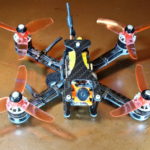


(click the images to enlarge)
Firstly the 3″ version: 132g (without battery)!
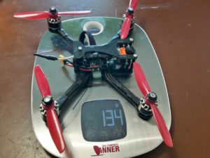
And secondly the 4″ variant weighting 134g (without battery)!
A small additional note by myself (fishpepper): In addition with the 104g 4S 800mAh SLS lipo battery Holgers build will end up at only 240g! There is enough room for a lot of dirt and grass that will accumulate in your copter and you are still legally safe as German law allows sub 250g copters for FPV flying.
Now enjoy your own sub250 copter without a spotting person (again, German law…)! Yeah!
Remember, despite their tin size those copters are still a power horse and are not suited for children. Flying indoor, especially in your living room, are not safe either (addition from myself: Holger do you still have those fancy looking black circle decoration on the ceiling of your living room? *g*) Those rotors can do serious cutting, “ruckzuck” and your children can only count to 4 or less with their own fingers.
The flight time depends on propeller, battery and flight style, times from 2 ½ to 4 minutes are feasible.The flying experience is intense, all freestyle maneuvers are possible. The V2 version of this frame is stable enough to be flown in close proximity to trees, I do fly them in a forest and through gates.
Those who prefer having a rock solid “Panzer” should have a look at the 3″ V1 in the dropbox folder.
Liebe Grüße,
Holger Landwehr
Thanks a lot for this build log holger! And now enjoy the build.


