The Problem
The Skyzone SKY-02 FPV goggles are great for FPV flying and i really love them. Unfortunately they have one really annoying “bug”: You can not select if you are using Li-Po or Li-Ion batteries. As both have different discharge characteristics the low-voltage beep comes way to soon. Mine goes off at arount 3.75V per cell (7.5V on 2S). That’s fine for Li-Po battery packs. I recently made my own Li-Ion battery packs using old Laptop Cells and they can be discharged much lower (absolute maximum is 2.5V !). Using the alarm at 3.75V per cell will waste 3/4 of their capacity!
 Hack it!
But now comes the hack: The Skyzone goggles use a simple resistor divider to measure the pack voltage (see the schematic on the right). This can be easily hacked to our needs. By modifying the resistor ratio we can alter the low voltage alarm level to better fit to Li-Ion cells.
The low-voltage alarm is activated at around 7.5V on the 2S setting. If you want to find a resistor value for a given 2S Voltage use the following formula:
![]()
Example: If you want the buzzer to start at ![]() this formula will give you a value for
this formula will give you a value for ![]() .
.
If you want to know the voltage for a given R that you found in your drawers use the following formula:
![]()
Example: For a given ![]() the low-voltage alarm will trigger on
the low-voltage alarm will trigger on ![]() (~3.2V cell voltage).
(~3.2V cell voltage).
Howto
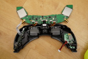
First of all disassemble the goggles. There are three screws and four plastic “hooks” on the front. Disconnect the white and the black&red cable connectors. Keep the flat cables going to the displays connected and gently flip over the main circuit board:
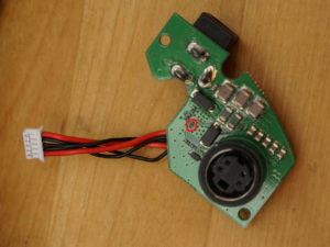
Remove the screws of the circuit board on the lower right and take it out of the case:
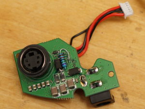
 The red marking shows the resistor we are going to replace. For a first test i wanted to change the low-voltage alarm threshold from 7.5V to ~7V. Therefore i replaced this resistor with a 75kΩ resistor. This gives us a low-voltage alarm of approximately 3.5V per cell. For an alarm at 3.2V per cell use a 68kΩ resistor instead. In order to do this, remove the resistor with a big blob of solder covering both sides. Now you can either solder in a 0402-sized smd resistor or take a normal wired one as i did:
 Connect one side to the diode where the trace comes from. The other side can be soldered to the other pad of the old resistor. Make sure that you do not short both pads! This could destroy your goggles as the ADC will see the full battery voltage instead of the allowed maximum of 3.3V!
Once you are done with the modification add a small hot-glue blob on top of the resistor to fixate it and remount the pcb. When closing the case make sure that you do not damage the flex connectors on the front! They get stuck in between the case and the plastic clips! You might want to test the low voltage alarm with a lab power supply. It should start beeping once you reach ~7.0V (when set to 2S batteries).
Have fun!


Hi. Awesome work btw. Was really looking forward to sorting this out and got the bits needed, only to discover on opening it up that I have a different version or revision. How do you go about working out which resistor to change or what the circuit is?
Send me a (high resolution) picture of the front and back of the pcb. Maybe I can figure it out 😉
simon AT fishpepper.de
Great thanks!
i’ll try a 127k Resistor for my 11.1V warning.